9-16 FLIGHT CONTROLS / ROLL CONTROLS
ICON A5 / MAINTENANCE MANUAL CHANGE C3
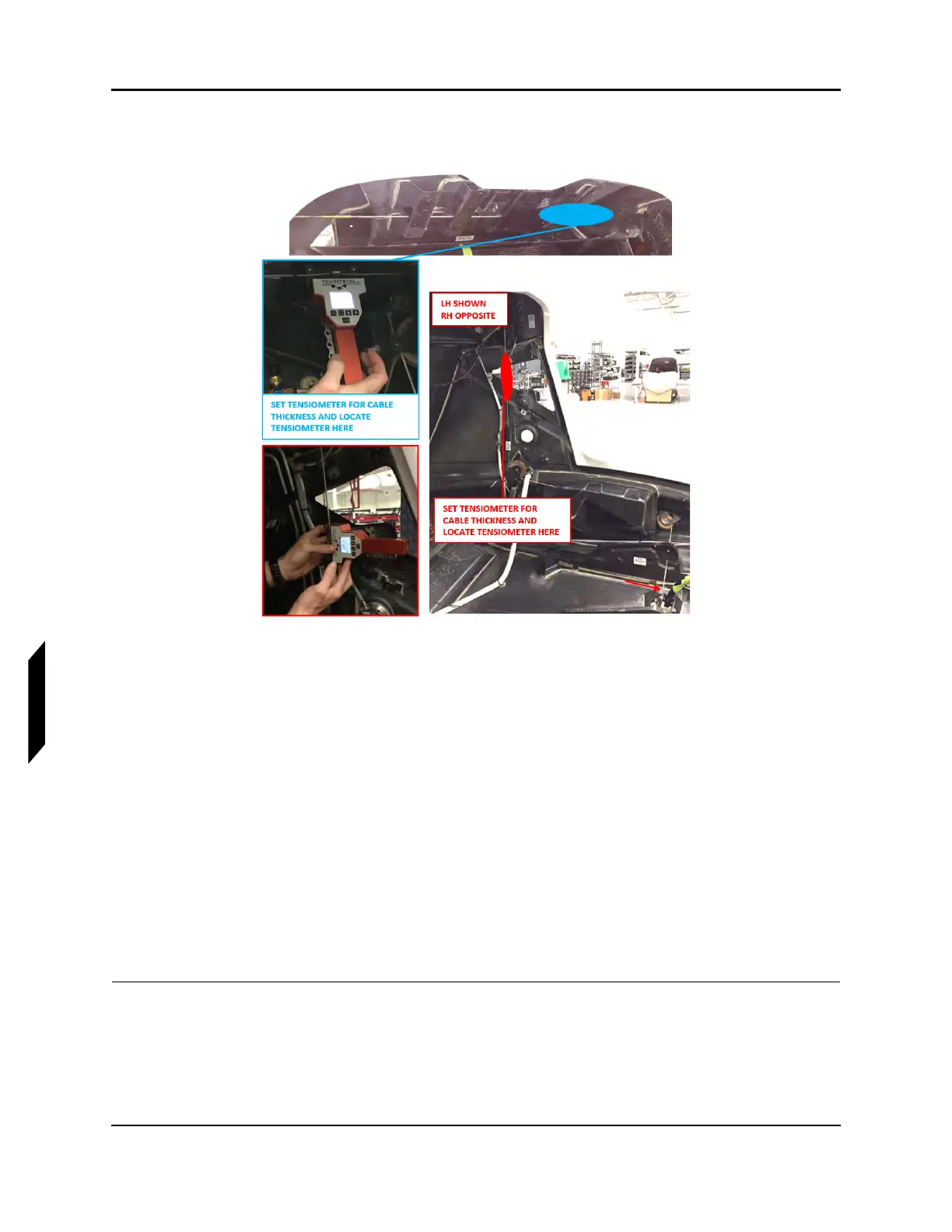
within 25-30 lb of tension. Refer to the manufacturers’ calibration card to correctly read cable
tension for the cable diameter.
FIGURE 9-12
TENSIOMETER LOCATIONS
9. Remove all installed rig pins:
a. 2X Wing socket bellcrank rig pins
b. Control stick rig pin
c. FWD pitch sector rig pin
10. Install seatbelt reel cover, left hand and right hand baggage sidewalls, and baggage headliner. If
the overhead console was removed, re-install. (See “Seat Belt Inertia Reel Installation” on page
3-40.) (See “Baggage Sidewall Panel Installation” on page 3-45.) (See “Headliner Installation” on
page 3-38.) (See “Removal and Installation of Inspection Panels and Fairings” on page 3-34.)
11. Install baggage floor boards using hardware retained during removal. (See “Baggage Floor Instal-
lation” on page 3-42.)
12. Install seat back and seat pan using hardware retained during removal. (See “Seat Back Installa-
tion” on page 3-51.) (See “Seat Pan Installation” on page 3-53.)
13. Install cockpit floor boards. (See “Cockpit Floor Board Installation” on page 3-47.)
VERIFICATION METHOD:
Record results and check against requirement. If requirement is not met complete aileron rigging. (See
“Rigging Roll Controls” on page 9-20.)