9-22 FLIGHT CONTROLS / ROLL CONTROLS
ICON A5 / MAINTENANCE MANUAL CHANGE C3
5. Remove aileron access panel. (See “Removal and Installation of Inspection Panels and Fairings”
on page 3-34.) Retain all fastening hardware.
6. Inspect all components within the roll circuit for excessive wear. Any components that show
excessive wear or damage must be replaced with new components. Refer to table for compo-
nent list.
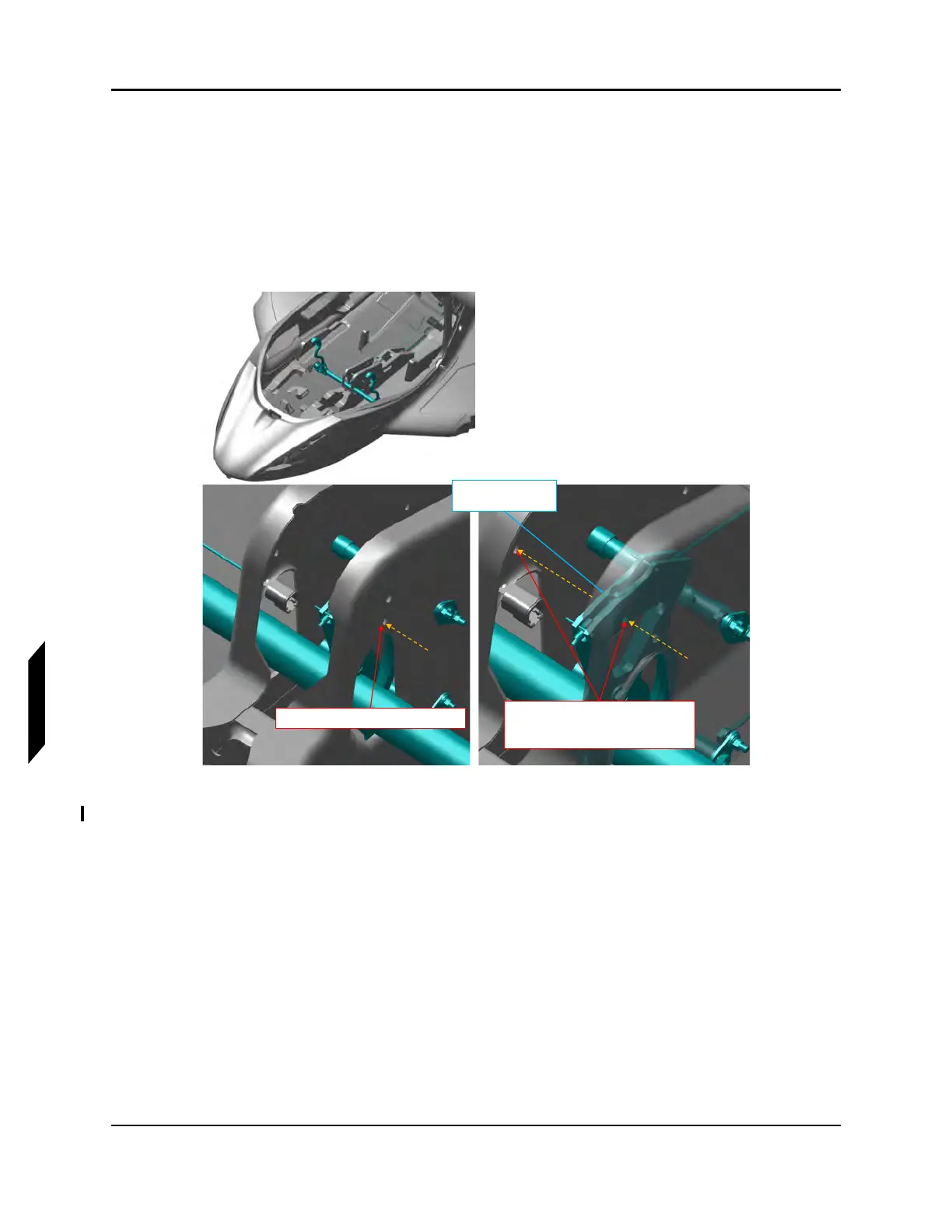
7. Install .250” diameter rig pin through the center console and forward pitch sector prior. See
Figure 9-14.
FIGURE 9-14
FWD PITCH SECTOR PIN LOCATIONS
8. Install .1875 in diameter rig pin through the control stick rig pin hole. See Figure 9-15.
Insert rig pin through hole in keel
Insert rig pin through hole in forward
pitch sector and through hole on
opposite end of keel
Fwd Pitch Sector
(Reference)