9-34 FLIGHT CONTROLS / ROLL CONTROLS
ICON A5 / MAINTENANCE MANUAL CHANGE C3
Install Upper Roll Cable
6. Remove upper roll cable.(See “Remove Roll Cables” on page 9-28.)
7. Temporarily separate the new upper roll cable by unthreading the turnbuckle that is connecting
both ends.
NOTE: When loosening the turnbuckle, ensure both ends of the cable are
held to avoid winding and damaging the new cable.
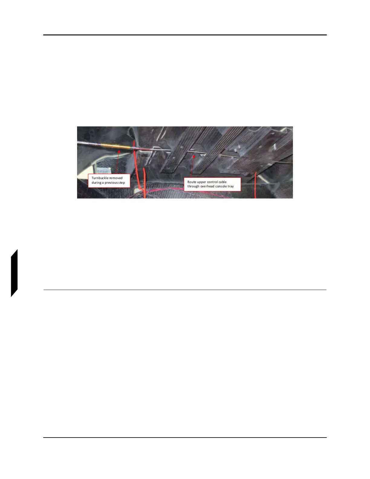
8. Route the upper control cable through the overhead console tray. (See Figure 9-26.) Careful not
to damage any electrical wires while routing the cable. Snaking the cable is permissible.
FIGURE 9-26
ROUTING UPPER CONTROL CABLE
9. Connect the upper control cable at the upper attachment point of the roll socket using new
locking nuts (MS21043-3). Tighten hardware to 20 in-lb.
10. Re-connect the upper control cable at the turnbuckle. Do not fully tension the cables during this
step.
NOTE: When tightening the turnbuckle, ensure both ends of the cable are
held to avoid winding and damaging the new cable.
11. Rig the roll system. (See “Rigging Roll Controls” on page 9-20.)
VERIFICATION METHOD:
The cables should be re-installed, and hardware torqued to the appropriate spec prior to rigging the
system. Tensions should meet the requirements of the rigging section.