FLIGHT CONTROLS / ROLL CONTROLS 9-33
CHANGE C3 ICON A5 / MAINTENANCE MANUAL
FIGURE 9-24
FUSELAGE ROLL CONTROL SYSTEM
1. Remove lower control cable. (See “Remove Roll Cables” on page 9-28.)
2. Starting from the center wing loosely route new lower roll cable from the roll socket to the torque
tube bearing. Use Figure 9-22 for routing path. (See “Roll Socket and Torque Tube Connection
Points” on page 9-30.)
3. If the roll pullies were removed, reinstall the bolts and torque to 48 in-lb. If the safety pins were
removed, re-install with a new MS25665-151 cotter pins. (See “Roll Pulley Exploded Views” on
page 9-33.)
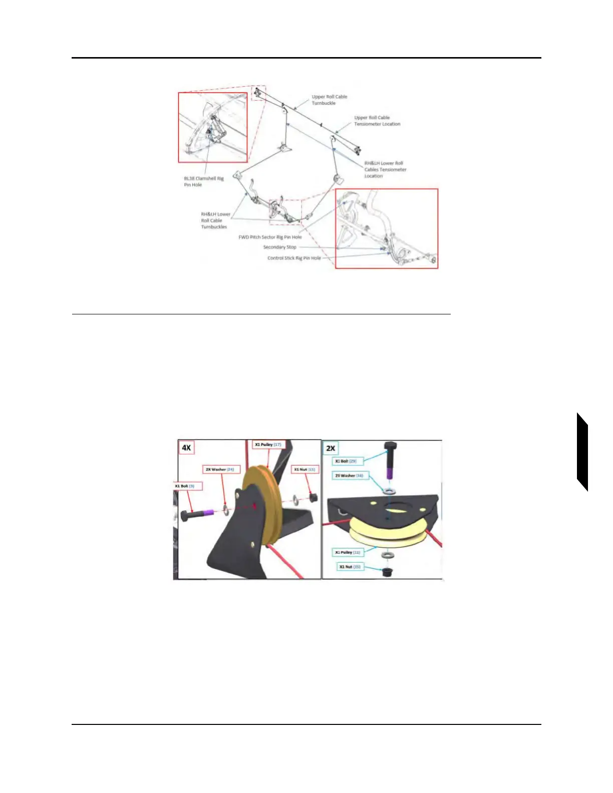
FIGURE 9-25
ROLL PULLEY EXPLODED VIEWS
4. Connect the lower roll cable to the lower roll socket attachment point using new locking nuts
(MS21043-3). Torque hardware to 20 in-lb.
5. Connect the roll cable to the rod end still attached to the cockpit control stick at the same time
as connecting to the roll cable such that the threads are balanced. Do not fully tension the cable
system during this step.
NOTE: Ensure that when tightening the turnbuckle that the cable is held as
to not wind the cable.