9-48 FLIGHT CONTROLS / PITCH CONTROLS
ICON A5 / MAINTENANCE MANUAL CHANGE C3
4. Remove baggage floor boards. (See “Baggage Floor Removal” on page 3-41.) Retain all fastening
hardware.
5. Remove fuel tank. (See “Remove Fuel Bladder (MY17 Only)” on page 10-11.) Retain all fastening
hardware.
6. Remove center console bucket and throttle bezel. (See “Center Console Bucket Removal” on
page 8-5.)(See “Throttle Handle and Bezel Removal” on page 8-10.) Retain all fastening hard-
ware.
7. Remove Horizontal Tail. (See “Horizontal Tail Removal” on page 12-11.) Retain all fastening hard-
ware.
8. Inspect all components within the pitch circuit for excessive wear. Any components that show
excessive wear or damage must be replaced with new components.
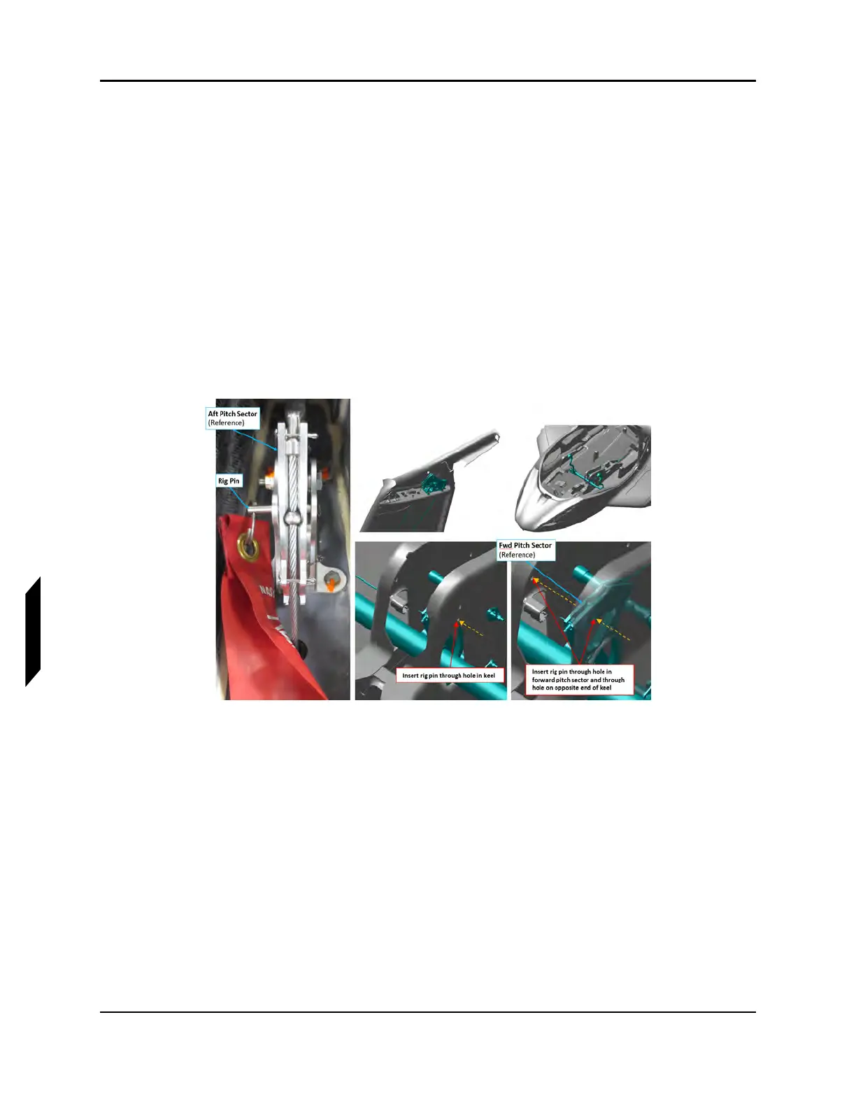
9. Install .250 in diameter rig pin through the center console and forward pitch sector. See Figure
9-33.
10. 10. Install .1875 in diameter rig pin through the aft pitch sector in the vertical tail. See Figure 9-33.
FIGURE 9-33
PITCH SYSTEM RIG PINS
11. Use a tensiometer at least 8 in away from turnbuckles to rig both the upper pitch control cable
and lower pitch control cable (cable thickness = 1/8 in). Adjust turnbuckles as required to set
cable tension to 20 – 35 lbs. Refer to Figure 9-34. Operate tensiometer per its manufacturer’s
instructions.