9-92 FLIGHT CONTROLS / YAW CONTROLS
ICON A5 / MAINTENANCE MANUAL CHANGE C3
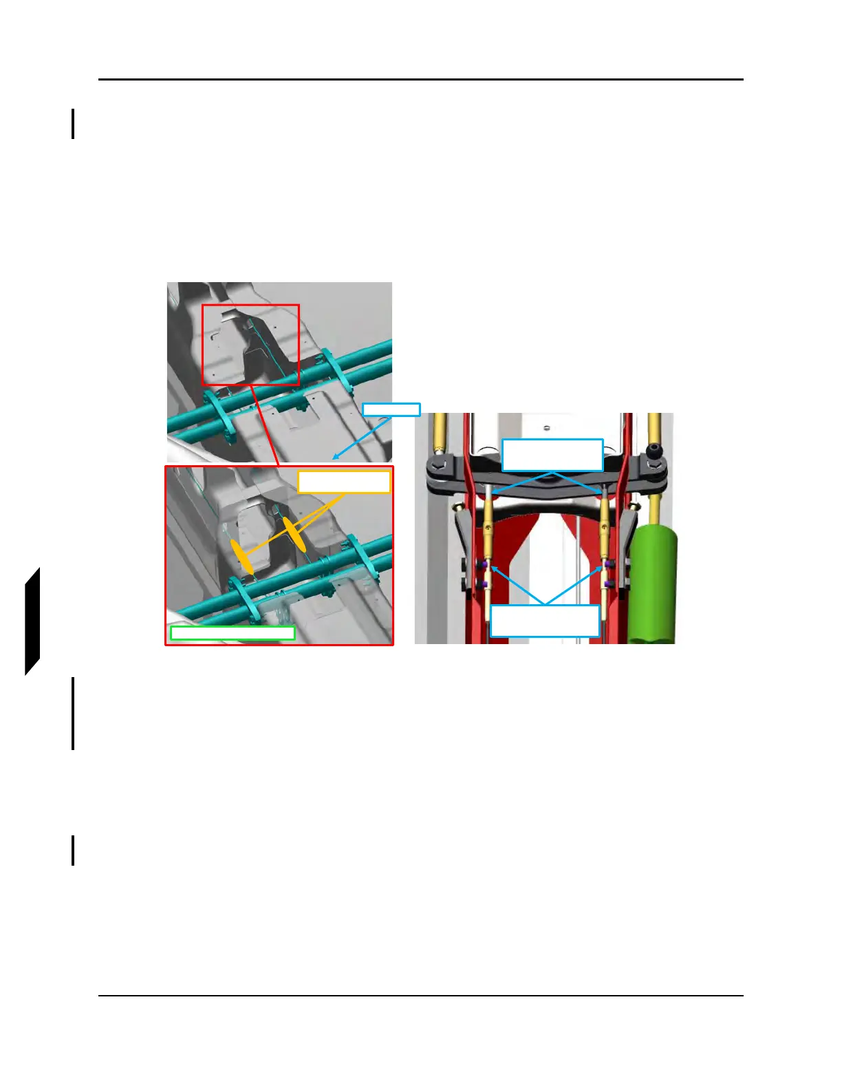
12. Use a tensiometer (cable thickness = 3/32 in) to rig both middle yaw control cables. To achieve
the following, refer to Figure 9-57:
a. Adjust inner set of turnbuckles to set cable tension on both cables to 5-12 lbs
b. Ensure 1 to 12 rod end threads are exposed after turnbuckle adjustment
c. Ensure that no more than 3 cable terminal threads are exposed after turnbuckle adjust-
ments
d. Ensure that water rudder remains centered 0° ± .5° relative to the BL_0 plane after rigging
is complete
FIGURE 9-57
MIDDLE YAW CIRCUIT
13. 13. Use a tensiometer to rig both AFT Yaw Control Cables (cable thickness = 1/8 in). Refer to the
tensiometer manufacturers’ calibration card to correctly read cable tension for the cable diam-
eter measured. To achieve the following, refer to Figure 9-58:
a. Adjust outer set of turnbuckles to set cable tension on both cables to 18-22 lbs
b. Ensure 1 to 16 rod end threads are exposed after turnbuckle adjustment
c. Ensure that no more than 3 cable terminal threads are exposed after turnbuckle adjust-
ments
d. Ensure that water rudder remains centered 0° ± .5° relative to the BL_0 plane after rigging
is completed
Ensure no more than 3 threads
are exposed on cable terminal
after adjustments
Ensure that only 1 to 12
threads are exposed on the
rod end after adjustments
Keel is shown transparent for clarity
Locate Tensiometer Here
Set tension to 5-12 lbs
Keel (reference)