FUEL SYSTEM / FUEL TANK (MY18+) 10-23
CHANGE C2 ICON A5 / MAINTENANCE MANUAL
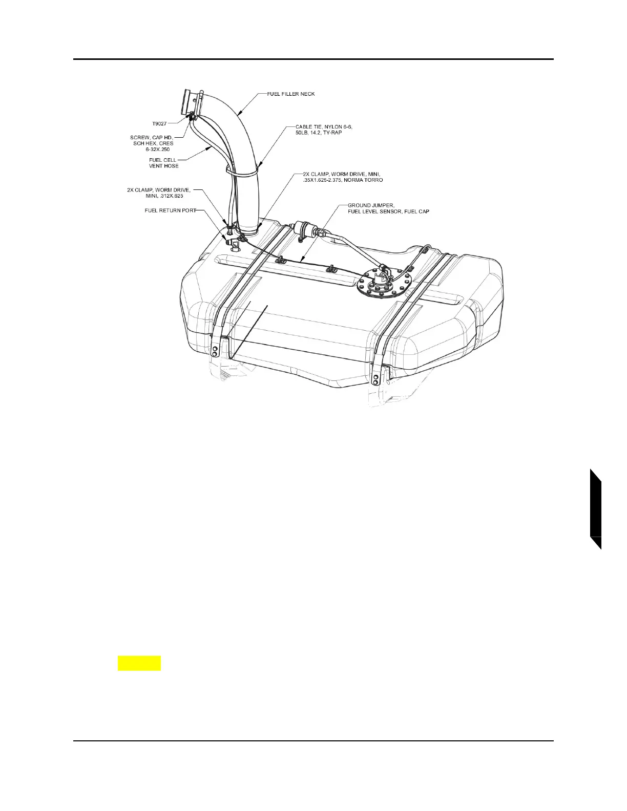
FIGURE 10-8
FUEL FILLER NECK INSTALL AND ELECTRICAL CONNECTIONS
8. Secure both ends of the fuel filler neck using worm drive clamps. (See Figure 10-8.) Position the
bottom hose clamp so that there is a .4”±.1” gap between the bottom edge of the hose clamp and
the top face of the fuel tank.
9. Torque both clamps to 10-13 in-lb.
10. Connect fuel cell vent hose to hose barb in fuel cap adapter using the mini worm drive clamp.
(See Figure 10-8.) Torque to 10-13 in-lb.
11. Connect fuel return line to the elbow fuel return port in the tank and torque to 110-130 in-lb with
a 11/16 wrench. (See Figure 10-8.)
12. Connect fuel line from fuel pump to coarse fuel filter. Torque fittings to 110-130 in-lb with a 11/16
wrench.
13. Secure T9027 ring terminal from ground wire on fuel tank subassembly to the filler cap adapter
using #6-32 cap screw. Torque screw to 9 in-lb. (See Figure 10-8.)
14. Secure fuel filler neck, ground wire, and fuel vent hose with CABLE TIE, NYLON 6-6, 50 LB.(See
Figure 10-8.)
CAUTION: Do not over tension cable tie and create a blockage or kink in fuel
vent hose.
15. Connect the optical switch connector to D9038P form fuselage wire harness.(See Figure 10-7.)
16. Connect the fuel level sensor connector to D9038P from fuselage wire harness.(See Figure
10-7.)