12-18 HORIZONTAL TAIL / HORIZONTAL TAIL GENERAL MAINTENANCE
ICON A5 / MAINTENANCE MANUAL CHANGE C1
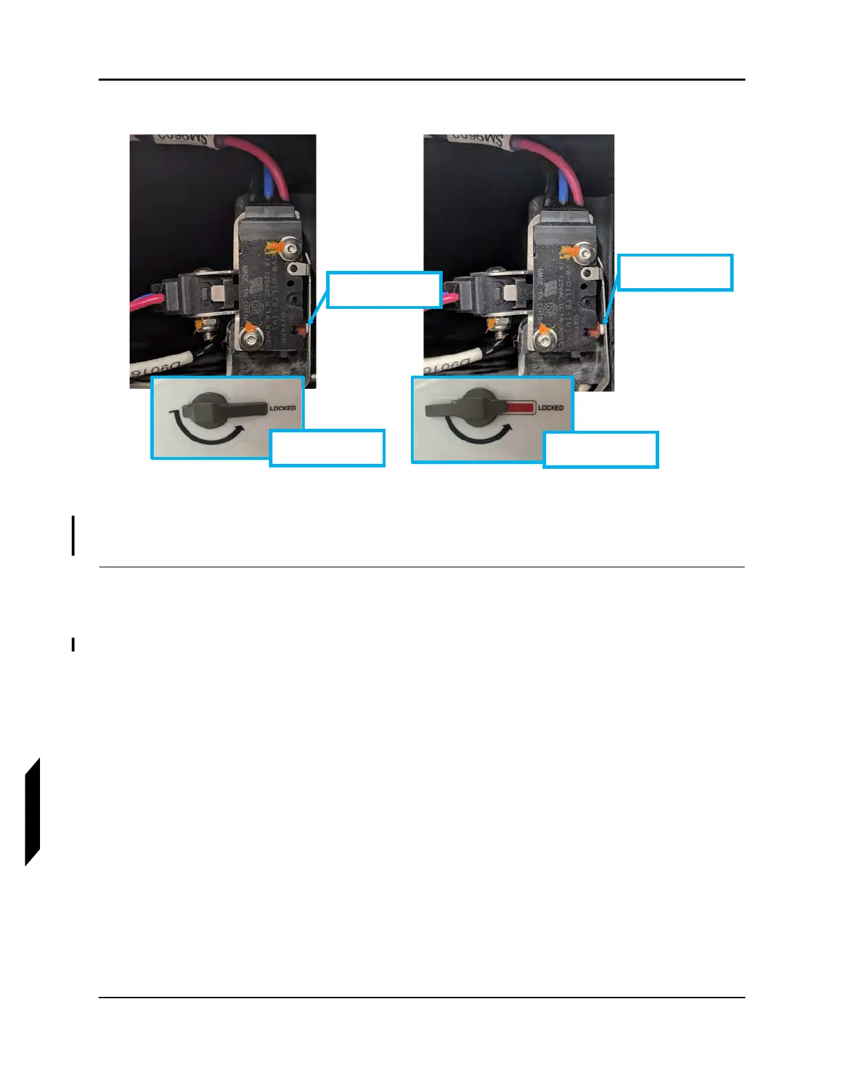
FIGURE 12-5
VERIFY SWITCH POSITION
4. Reinstall access panel. See Figure 12-2. Torque screws to 6.5-8.0 in-lbs.
VERIFICATION METHOD:
Once the two limit switches are installed and functional, this task is complete.
RELATED INFORMATION:
"Horizontal Tail Removal" on page 12-11
"Removal and Installation of Inspection Panels and Fairings" on page 3-34
"Remove Horizontal Tail Tip Lock Switches" on page 12-6
LH switch in the
“unlocked” position
LH handle in
“unlocked” Position
LH switch in the
“locked” position
LH handle in
“locked” Position