13-62 INSTRUMENTS (AND AVIONICS) / VHF COMM ANTENNA
ICON A5 / MAINTENANCE MANUAL CHANGE C2
13.6 VHF Comm Antenna
13.6.1 VHF Comm Antenna Description
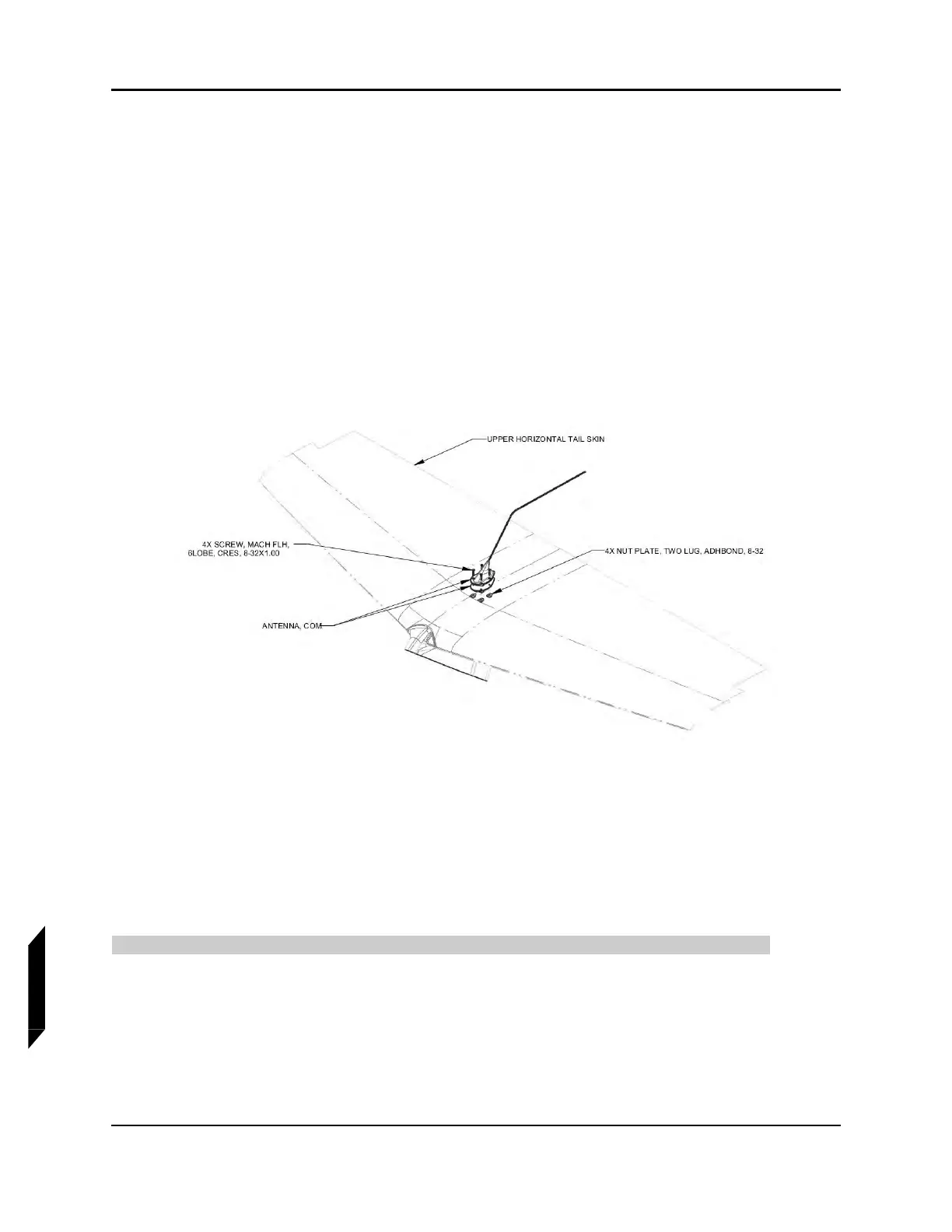
The comm antenna is located on top of the horizontal tail and works in conjunction with the VHF radio
located in the front of the aircraft. (See Figure 13-18.) The antenna transmits on the VHF radio spec-
trum—also known as aircraft band. This allows for communication between air traffic control and
aircraft pilot.
13.6.2 VHF Comm Antenna Diagram/Schematic
FIGURE 13-18
COMM ANTENNA—EXPLODED VIEW
13.6.3 Maintenance Instructions
13.6.3.1 Comm Antenna Removal
These instructions are to be used to remove the comm antenna for transportation or repair.
TASK INFORMATION:
Type of Maintenance
Line
Level of Certification