14-22 LANDING GEAR / BRAKE LINE
ICON A5 / MAINTENANCE MANUAL CHANGE C2
Parts Required
HDB01 Stainless Steel Braided Brake Hose
HYD-008P B-nut or HEA01 Banjo fittings as required
T25F-C0 Spiral Wrap
TY24MX Cable Tie
Aircraft System and Number
11—Landing Gear
Consumables
F4TAPEBLACK Silicone Tape
Smooth-On Sil-Poxy
The two connector lines that run between pilot and co-pilot master cylinders are identical. Use the
procedure below to replace either of them.
1. Cut and remove the cable tie holding the center of the brake lines to the structure.
2. Disconnect the brake line by using an 11mm wrench to hold the HYD-006P adapter fitting in the
brake cylinders and a 1/2 inch wrench to spin off the B-nut on both ends of the line. Cap or plug
the openings to minimize fluid loss. Remove the line.
3. Cut a 36.5-inch length of brake hose.
4. Terminate both ends of the hose with HYD-008P B-nut fittings. (See “General Brake Line Termi-
nation Procedure” on page 14-29.)
5. Wrap the entire length of each brake line with spiral wrap.
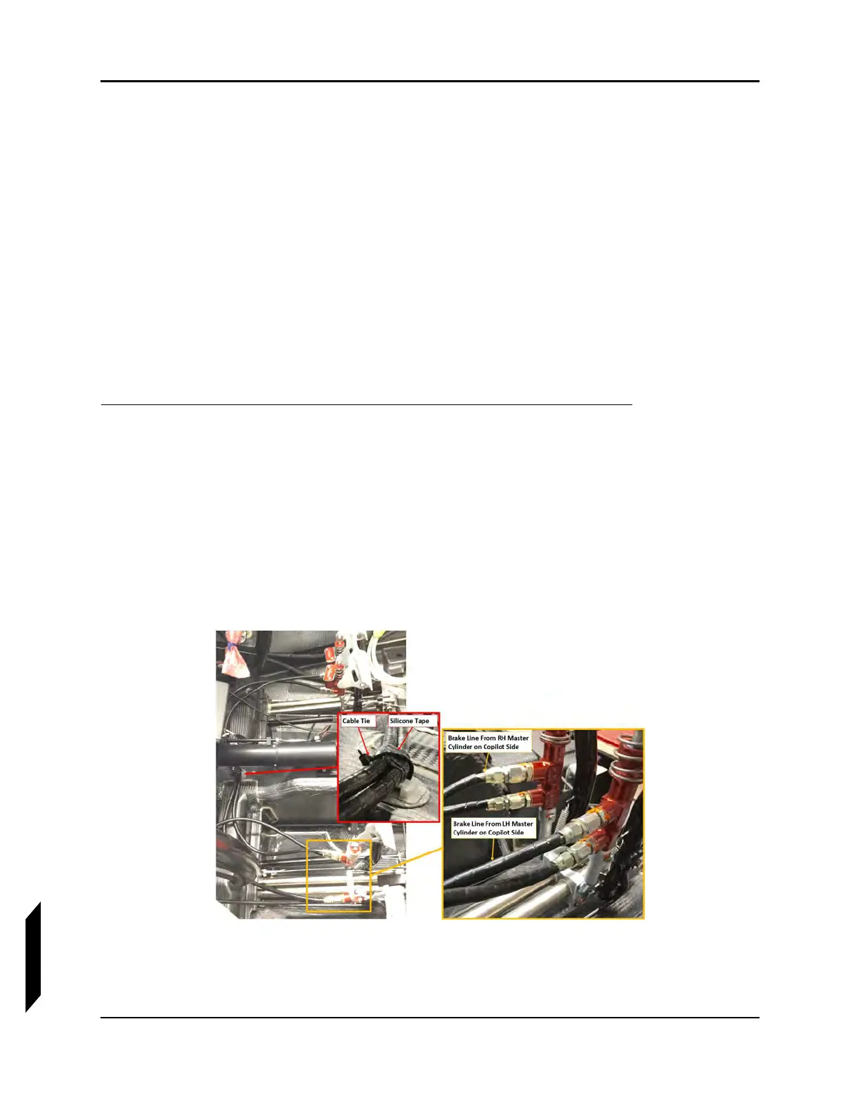
6. Route the line as shown in Figure 14-6.
FIGURE 14-6
BRAKE LINE REPLACEMENT
7. Connect the brake line to the adapter fittings on the master cylinders.