LANDING GEAR / BRAKE LINE 14-27
CHANGE C2 ICON A5 / MAINTENANCE MANUAL
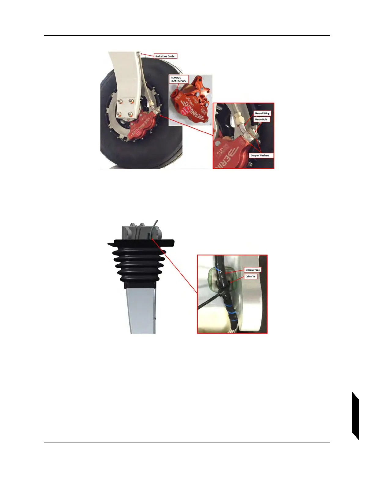
FIGURE 14-8
MAIN LANDING GEAR
11. Cut a 3-inch length of silicon tape and wrap it around the brake line at the location of the MLG
trunnion cable tie mount. Use a TY24MX cable tie to secure the line to this mount. See Figure
14-9.
FIGURE 14-9
MAIN LANDING GEAR TRUNNION
12. Seal the slot where the brake line passes through the MLG boot by injecting Sil-Poxy into the joint
and completely around the line. Leave a small fillet of Sil-Poxy all around the joint to ensure a
good water seal.
13. For the right hand brake line only: locate the two cable tie mounts on the aft bulkhead used to
secure the line. Mark the location on the brake line that will secured to the mounts. Wrap a 3-inch
length of silicone tape around the brake line at each mount location, then secure the line to the
mounts using TY24MX cable tie at each of the two locations (see Figure 14-10).