14-28 LANDING GEAR / BRAKE LINE
ICON A5 / MAINTENANCE MANUAL CHANGE C2
FIGURE 14-10
BRAKE LINE REPLACEMENT
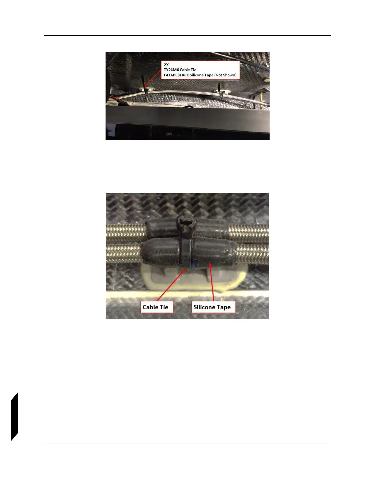
14. Route the brake line to the parking brake valve. Use the above method to wrap the brake line with
silicone tape and attach with a cable tire at each mounting point on the structure. Figure 14-11
shows a typical mount.
FIGURE 14-11
PARKING BRAKE VALVE
15. Trim excess length from the brake line if desired and terminate the parking brake valve end of
the line with a HYD-008P B-nut fitting. (See “General Brake Line Termination Procedure” on
page 14-29.)
16. Connect the brake line B-nut to the parking brake valve, then use a 7/16 wrench to hold the
AN816-3D fitting on the forward port of the parking brake valve, and a 1/2 wrench to torque the
B-nut to 30-40 in-lb
f
(see Figure 14-12).