14-26 LANDING GEAR / BRAKE LINE
ICON A5 / MAINTENANCE MANUAL CHANGE C2
4. The brake line end fitting cannot pass through the hole in the forward main bulkhead or through
the guides on the aft face of the Main Landing Gear (MLG) leg, so use a pair of wire or hose
cutters to cut the brake line just aft of the parking brake B-nut fitting.
5. Remove the brake line by guiding it through the bulkhead, MLG boot and MLG leg guides, pulling
on the banjo end. The line is bonded with Sil-Poxy at the boot joint; work this interface being
careful to not damage the boot.
6. If replacing the aft-left brake line, cut a length of hose to 114.0-inches. If replacing the aft-right
brake line, cut a length of hose to 126.0-inches. Before cutting, wrap the cut location with
masking tape, then cut through the tape. This will result in a neater cut of the stainless braid,
making it easier to pass the hose through the MLG leg guides.
7. Terminate one end of the hose with a HYD-008P B-nut fitting. (See “General Brake Line Termi-
nation Procedure” on page 14-29.)
8. Starting near the appropriate brake caliper, thread the unterminated end of the brake line
through the lower and upper MLG leg guides then through the clearance slot in the MLG boot
and on into the MLG bay.
9. Continue routing the line under all the MLG components and through the appropriate side
(LH/RH) MS35489-35 grommet in the forward main bulkhead Forward Main Bulkhead.
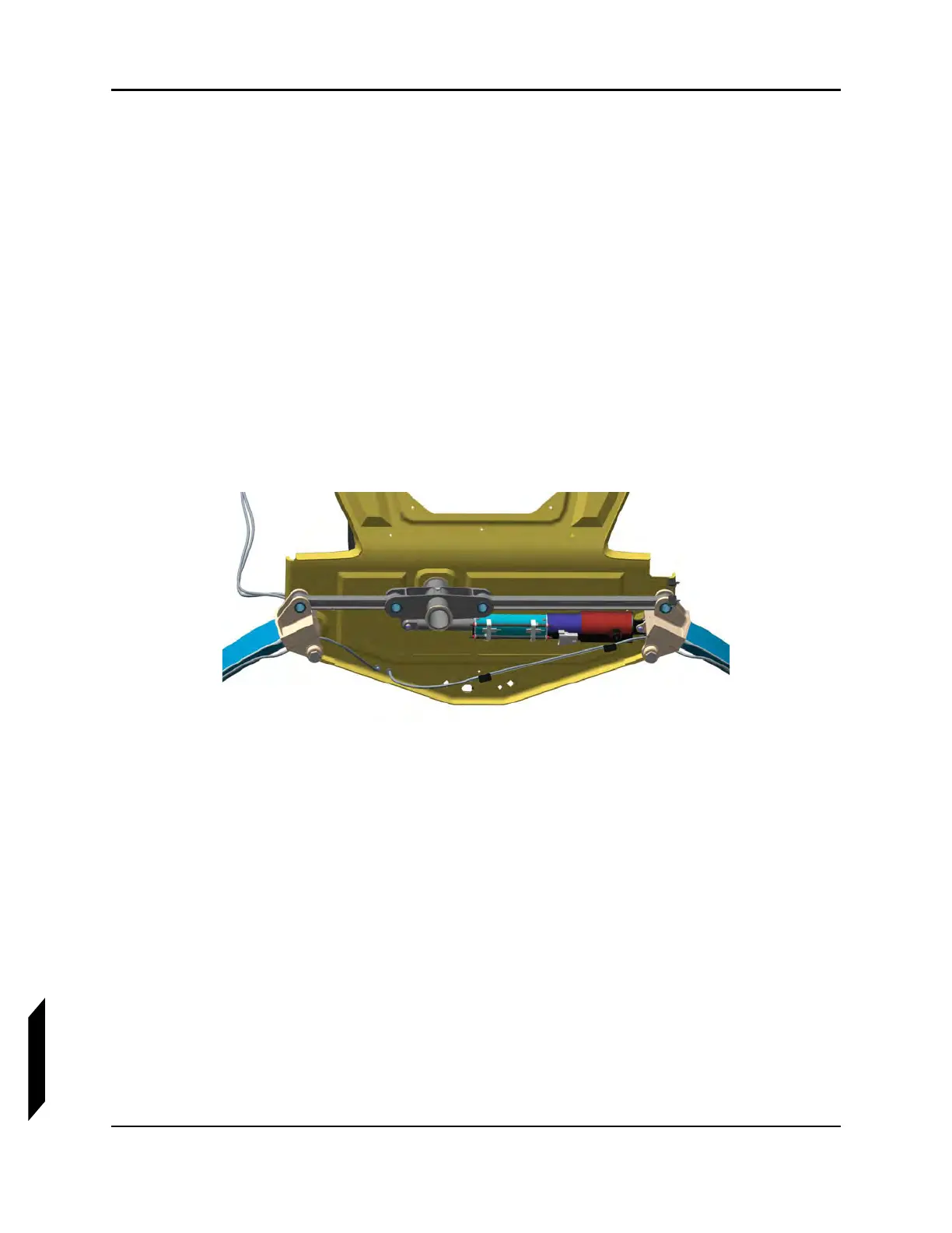
FIGURE 14-7
FORWARD MAIN BULKHEAD
10. Connect the banjo fitting end of the brake line to the caliper, routing the line in a natural way up
through the MLG leg guides. Do not put a twist in the line. Use a HYD-003P Banjo bolt and two
HYD-005B copper washers as shown in Figure 14-8. Torque the Banjo bolt to 140 in-lb
f
.