WING / WING LOCK 17-29
CHANGE C2 ICON A5 / MAINTENANCE MANUAL
3. Use a T15 Torx drive to remove the three 8-32 flush-head screws that attach the wing lock
handle mounting boss to the fuselage BL38 Rib.
4. Remove the wing lock handle and attached components from the fuselage BL38 Rib by rotating
the handle far enough to withdraw the wing lock cross pins from the pin sockets.
5. Proceed with the following further disassembly steps as necessary:
a. There are two link rods attached to the lock handle with a total of four ICA008144 pivot
pins and 98410A110 retaining rings. Remove each of these, making note of the pin orienta-
tion.
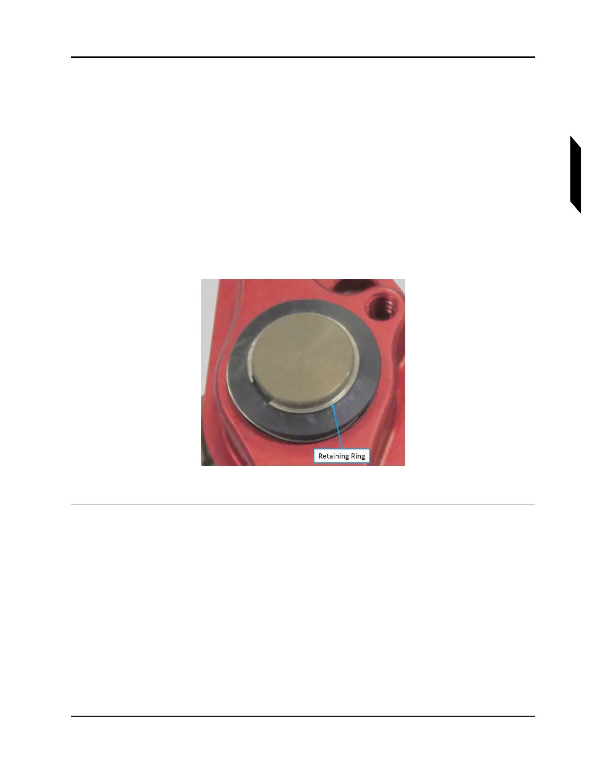
b. Remove the ICA011333 retaining ring from the shaft of the mounting boss (see Figure 17-6)
c. Remove the spacer, wave spring, and plastic washer from the shaft.
d. Slide the mounting boss out of the handle.
e. Press the wing lock bushing out of the handle if necessary, making note of its orientation.
f. Use a slot-head screwdriver to remove thee spring detent from the handle.
FIGURE 17-6
WING LOCK HANDLE
VERIFICATION METHOD:
The procedure is complete when the wing lock handle has been removed.