WING / WING LOCK 17-31
CHANGE C2 ICON A5 / MAINTENANCE MANUAL
2. If the lock handle components were disassembled, proceed with the below steps as necessary:
a. Apple LOCTITE
®
222™ to the threads of a new 3408A112 spring detent then, using a
slot-head screwdriver, thread it into the handle to a depth of.030-.005 inches (Figure 17-8).
b. Install the ICA008149 wing lock bushing into the handle, aligning the notches in the bushing
to the holes in the handle.
c. Insert the ICA011209(RH)/ICA022210(LH) wing lock mounting boss into the ICA008149
wing lock bushing.
d. Verify that the 90145A488 dowel pin, wing lock bushing, and wing lock mounting boss are
installed in the ICA007497(RH)/ICA007500(LH) wing lock handle as shown in Figure 17-9.
The detent ball should run in the groove in the mounting boss.
e. Place a 98090A365 plastic shim on the mounting bass shaft, followed by a 9714K999
wave spring and ICA008147 spacer as shown in Figure 17-10. Orient the spacer with its
beveled side facing away from the handle as shown.
f. Install an ICA011333 retaining ring into the groove in the wing lock mounting boss to hold
the above parts in place (Figure 17-6).
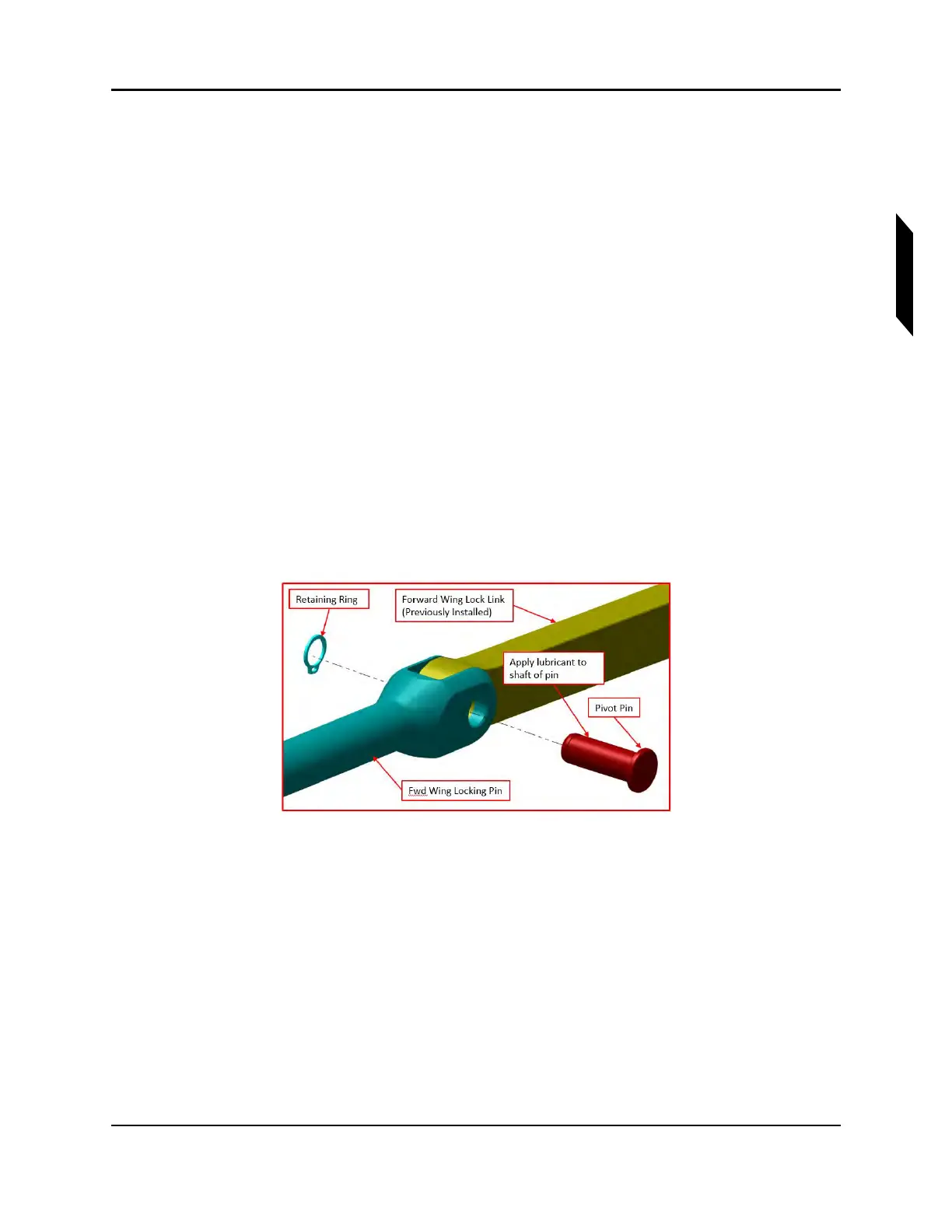
g. Attach the ICA008143 and ICA008148 link rods to the handle and locking pins. Coat each
ICA008144 pivot pin with MOLYKOTE™ on assembly. See Figure 17-7 for a typical instal-
lation. Verify correct pin orientation; the retaining rings are installed on the same side as
the wing lock bushing flange and mounting boss flange. Also, note that the longer the two
links and the longer the two locking pins connect and face aircraft forward, and the shorter
the two, face aircraft rearward.
FIGURE 17-7
WING LOCK HANDLE INSTALLATION