Design Guide 189
Schematic Checklist
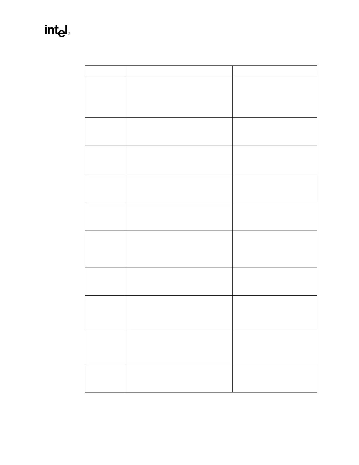
DSTBN[3:0]#
4
DSTBP[3:0]#
5
• Connect to both processors and the MCH. • Data strobe used to latch in
D[63:0]#
3
.
• Maintain a 25 mil spacing from
other signals.
• AGTL+ Strobes.
• Refer to Section 5.1.
FERR# • Connect to both processors and ICH3-S.
Pull-up at both ends of the signal with
56
Ω ± 5% to VCC_CPU.
• Asserted by processor to indicate
floating-point error.
• Async. GTL+.
• Refer to Section 5.3.1.
HIT# • Connect to both processors and the MCH.
• Wired-OR signal: Route as common clock
signal.
• Convey transaction snoop
operation results.
• AGTL+ Common Clock I/O.
• Refer to Section 5.2.
HITM# • Connect to both processors and the MCH.
• Wired-OR signal: route as common clock
signal.
• Convey transaction snoop
operation results.
• AGTL+ Common Clock I/O.
• Refer to Section 5.2.
HLOCK#
(LOCK#)
• Connect to both processors and the MCH. • Indicates to the system that a
transaction must occur atomically.
• AGTL+ Common Clock I/O.
• Refer to Section 5.2.
IERR# • If supported, connect to both processors and
the ICH3-S. Terminate at both ends with
56
Ω ± 5% pull-up to VCC_CPU.
• If not supported, leave as no-connect or
connect to a Baseboard Management
Controller (BMC).
• Asserted by the processor to
indicate an internal error.
• Asynchronous GTL+ Output.
• Refer to Section 5.3.1.
IGNNE# • Connect to both processors and ICH3-S.
Include 200
Ω ± 5% pull-up to VCC_CPU.
• Asserted to processor to ignore
numeric error.
• Asynchronous GTL+ Input.
• Refer to Section 5.3.2.
INIT# • Connect to both processors, FWH and
ICH3-S. Include 200
Ω ± 5% pull-up to
VCC_CPU.
• Voltage translator circuit is required for FWH.
• Resets processor internal
registers without affecting internal
caches. Also used to enable BIST.
• Asynchronous GTL+ Input.
• Refer to Section 5.3.2.2.
LINT1
LINT0
• Connect to both processors and ICH3-S.
Include 200
Ω ± 5% pull-up to VCC_CPU.
• Used as local APIC interrupts
when APIC is enabled.
• Map to INTR and NMI in ICH3-S.
• Asynchronous GTL+ Input.
• Refer to Section 5.3.2.
MCERR# • Connect to both processors and the MCH.
• Wired-OR signal: Route as common clock
signal.
• Convey transaction snoop
operation results.
• AGTL+ Common Clock I/O.
• Refer to Section 5.2.
Table 13-1. Processor Schematic Checklist (Sheet 3 of 6)
Checklist Items Recommendations Comments