Schematic Checklist
190 Design Guide
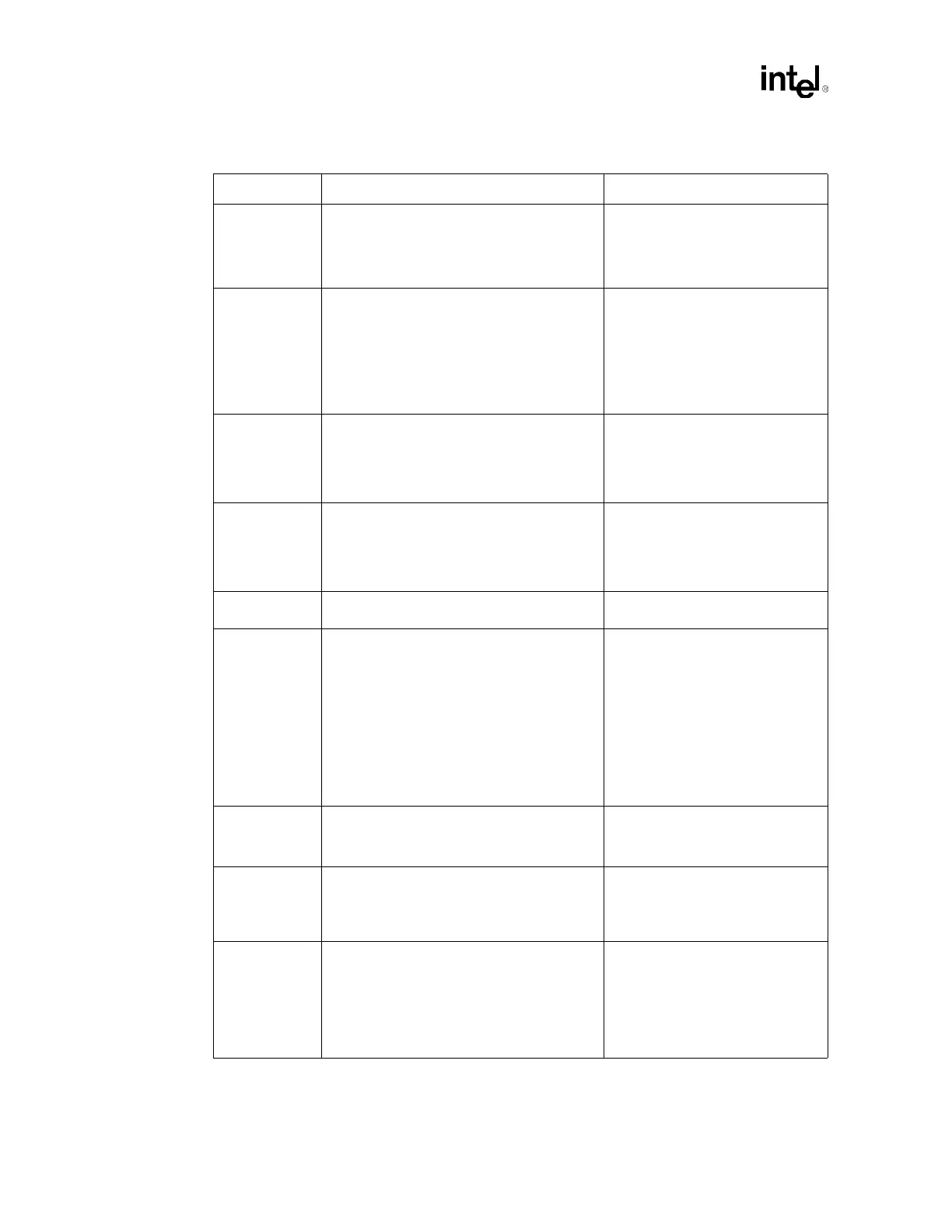
ODTEN • Enable on-die termination (ODT) on
Processor 0 (end processor) by pulling up to
VCC_CPU with a 50
Ω ± 20% resistor.
• Disable ODT for Processor 1 by pulling down
to V
SS
with a 50 Ω ± 20% resistor.
• Enables processor on-die
termination.
• Input.
• Refer to Section 5.3.7.
PROCHOT# • Pull-up at both ends of PROCHOT# with a
56
Ω ± 5% to VCC_CPU.
• Connect to both processors and ICH3-S
GPIO or a baseboard management
controller (BMC) if implemented in the
platform. A BMC can connect individually to
each processor in order to determine which
processor asserted PROCHOT#.
• Indicates the processor Thermal
Control Circuit has been
activated.
• Asynchronous GTL+ Output.
• Refer to Section 5.3.1.
PWRGOOD
(CPUPWRGOOD)
• Recommend 300
Ω ± 5% pull-up to
VCC_CPU. Connect to both processors and
ICH3-S.
• Asynchronous GTL+ Input.
• Asserted by ICH3-S when all
processor voltage supplies are
stable.
• Refer to Section 5.3.2.1.
REQ[4:0]#
6
• Connect to both processors and the MCH. • Asserted by current bus owner to
define the currently active
transaction type.
• AGTL+ Source Synchronous I/O.
• Refer to Section 5.1.
Reserved • Reserved signals must remain as No
Connect (NC).
RESET#
7
• Recommend 51 Ω ± 5% pull-up to
VCC_CPU. Connect to MCH and both
processors. Note that this signal is dual
terminated at both ends of transmission line.
• Resets all processors to known
states and invalidates caches
without writing back their
contents.
• AGTL+ Common Clock Input.
• Refer to Section 5.2.2.
• If using ITP, for signal connection
to ITP, refer to the
ITP700 Debug
Port Design Guide
for all
schematic, layout and routing
recommendations.
RS[2:0]# • Connect to both processors and the MCH. • Driven by response agent.
• AGTL+ Common Clock Input.
• Refer to Section 5.2.
RSP# • Connect to both processors and the MCH. • Provides parity for RS[2:0]#
signals.
• AGTL+ Common Clock Input.
• Refer to Section 5.2.
SKTOCC# • If supported, pull-up to VCC_3.3; otherwise
leave as NC.
• Power/Other
• Output of this signal indicates
whether a processor is installed or
not; prevents powering up the
voltage regulators for the
processors.
• Refer to Section 5.3.9.
Table 13-1. Processor Schematic Checklist (Sheet 4 of 6)
Checklist Items Recommendations Comments