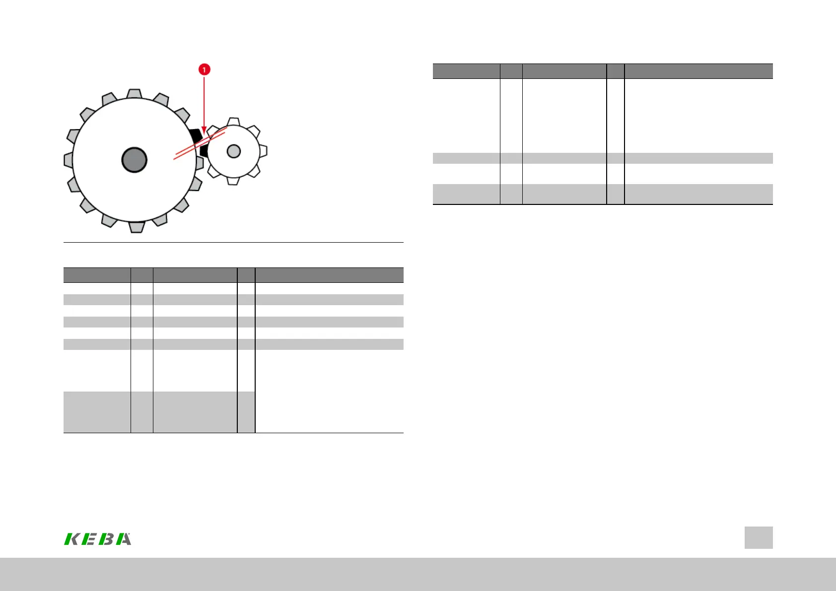
Image 6.11: Mechanical system axis correction (① = slack in gearing)
P No. Index Name / Setting Unit Description
530 0 ENC_Encoder1Sel Channelselectionforthe1stencoderused
531 0 ENC_Encoder2Sel Channelselectionforthe2ndencoderused
590 0 ENC_ACOR_Sel
0(=OFF) Noencoderselected
1(=1stEncoder) 1.encoderselected
2(=2ndEncoder) 2.encoderselected
591 0 ENC_ACOR_PosStart Definitionofcorrectionrange:Therangeis
definedbyparametersP 0591 ENC_ACOR_
PosStartStartpositionand
P 0592 ENC_ACOR_PosEndendposition.
Thestartpositionisuser-specified;theend
positionisdeterminedonthedevicesidefrom
themaximumvalueofcorrectiontable
interpolationpointsusedandtheinterpolation
pointpitch.
592 0 ENC_ACOR_PosEnd
Table 6.36: Axis correction parameters
ID No.: 0842.26B.5-01Date: 09.2020
ServoOne- Device Help
103
6 Encoder
P No. Index Name / Setting Unit Description
593 0 ENC_ACOR_PosDelta Interpolationpointpitch:Thepositionsatwhich
thecorrectioninterpolationpointsareplottedare
definedviaparametersP 0593 ENC_ACOR_
PosDeltaInterpolationpointpitchandP 0591
ENC_ACOR_PosStartStartposition.Between
thecorrectioninterpolationpoints,the
correctionvaluesarecalculatedbycubicspline
interpolation.
594 0 ENC_ACOR_Val Actualposition
595 0-250 ENC_ACOR_VnegTab Valuesofthecorrectiontablefornegative
directionofrotationinuserunits.
596 0-250 ENC_ACOR_VposTab Valuesofthecorrectiontableforpositive
directionofrotationinuserunits.
Table 6.36: Axis correction parameters (continue)