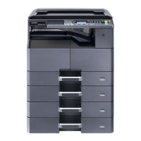
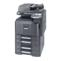
2WA/2NJ/2RK-1
2-1 Environment ............................................................................................................................. 2-1
2-2 Installing the main unit .............................................................................................................. 2-2
(1) Unpacking and checking bundled items .............................................................................. 2-4
(1-1) Machine...................................................................................................................... 2-4
(1-2) Take out of the machine unit ...................................................................................... 2-5
(1-3) Take out of fixed tape and cushioning material.......................................................... 2-7
(2) Notes on main unit transportation........................................................................................ 2-7
(3) Change to the operation unit position.................................................................................. 2-8
(4) Toner collection box attaching........................................................................................... 2-10
(5) Release the lock of the scanner mirror frame.................................................................... 2-12
(6) Release of lift plate stopper ............................................................................................... 2-13
(7) Release the lock of developer waste outlet ....................................................................... 2-14
(8) Affixing the operation panel sheet (220 to 240V models only) .......................................... 2-16
(9) Installation of the metal fittings to prevent falling down ..................................................... 2-17
(10) Connecting the Interface Cable ......................................................................................... 2-18
(11) Connecting the FAX cable (FAX installation only)............................................................. 2-21
(12) Loading Paper ................................................................................................................... 2-24
(12-1) Precaution for Loading Paper................................................................................... 2-24
(12-2) Set paper in the cassette.......................................................................................... 2-25
(12-3) Set paper in the large capacity feeder...................................................................... 2-29
(12-4) Set paper in the side feeder ..................................................................................... 2-35
(13) Connecting the Power Cord .............................................................................................. 2-37
(14) Input of the power source .................................................................................................. 2-38
(15) Setting up the Toner Container ......................................................................................... 2-39
(16) Default Setting ................................................................................................................... 2-42
(16-1) Setting Date and Time.............................................................................................. 2-42
(16-2) Network Setup (LAN Cable Connection).................................................................. 2-43
(16-3) Paper size and media type setting ........................................................................... 2-43
(17) Installing Software ............................................................................................................. 2-43
(18) Image adjusting ................................................................................................................. 2-44
(18-1) Set up in a high altitude............................................................................................ 2-44
(18-2) Setting the ID correction operation (Maintenance mode U464) ............................... 2-44
(18-3) Adjusting the halftone automatically (Maintenance mode U410) ............................. 2-45
(18-4) Output Maintenance report (Maintenance mode U000) ........................................... 2-45
(18-5) Clearing the counts (Maintenance mode U927)....................................................... 2-45
(18-6) Setting the delivery date (Maintenance mode U278) ............................................... 2-45
(19) Cassette heater control setting (100V model only)............................................................ 2-46
(20) Exiting from the maintenance mode .................................................................................. 2-46
(21) Completion of installing the main unit (Turning the power off) .......................................... 2-46
(22) Turn the power on again.................................................................................................... 2-46
2-3 Installing the optional equipment ............................................................................................2-47
(1) Gigabit Ethernet extension kit (IB-50)................................................................................ 2-47
(2) Wireless LAN interface kit(IB-51) ...................................................................................... 2-50
(3) Wireless LAN interface (IB-35) (120V model standard) .................................................... 2-52
(4) Document table (DT-730(B)) ............................................................................................. 2-56
(5) Numeric keypad (NK-7100 / NK-7110).............................................................................. 2-62
(6) IC card reader.................................................................................................................... 2-64
(7) USB keyboard (120V /220 to 240V model only)................................................................ 2-71
(8) Handset (100V model only) ............................................................................................... 2-79
(8-1) When attaching the main unit directly ...................................................................... 2-79
(8-2) In case installing the document table ....................................................................... 2-89
(9) Cassette heater ................................................................................................................. 2-99

 Loading...


