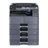
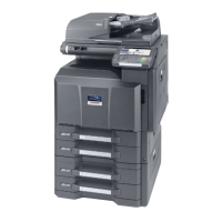
2WA/2NJ/2RK
(23) Data is not printed out due to the printer driver setting.................................................... 7-577
(24) Data is not printed out due to the printer driver setting.................................................... 7-577
(25) The printed image is partly missing ................................................................................. 7-578
(26) "Paper Mismatch Error" appears ..................................................................................... 7-578
7-8 Abnormal Noise .................................................................................................................... 7-579
(1) Abnormal sound occurs (Basic Measures)...................................................................... 7-580
(2) Abnormal sounds from the paper conveying section....................................................... 7-580
(3) Abnormal sound from the developer section ................................................................... 7-580
(4) Phenomenon 1 ................................................................................................................ 7-581
(5) Abnormal sound from the eject section ........................................................................... 7-581
(6) Fan rotating sounds are noisy ......................................................................................... 7-582
(7) Abnormal sound from the primary paper feed section..................................................... 7-582
(8) Abnormal sound from the machine front side.................................................................. 7-582
(9) Abnormal sound from the lower side than the fuser eject section ................................... 7-583
(10) Abnormal sound from the upper side of the fuser eject section ...................................... 7-583
(11) Abnormal sound from the fuser section........................................................................... 7-583
(12) Abnormal sound from inside the machine ....................................................................... 7-584
(13) Abnormal sound from inside the machine ....................................................................... 7-584
(14) Abnormal sound from inside the machine ....................................................................... 7-584
(15) The drive sounds are noisy during printing...................................................................... 7-585
7-9 Malfunction ........................................................................................................................... 7-586
(1) The cassette paper size is misdetected .......................................................................... 7-586
(2) The paper size loaded in the paper deck of the large capacity feeder is misdetected. ... 7-587
(3) The MP tray paper size is misdetected. ......................................................................... 7-588
(4) The controller fan motor does not rotate ......................................................................... 7-588
(5) The developer fan motor does not rotate ........................................................................ 7-589
(6) The main unit malfunctions even if turning on the power switch ..................................... 7-589
(7) Toner falls over the paper conveying section .................................................................. 7-590
8PWBs
8-1 Description for PWB ................................................................................................................. 8-1
(1) Main PWB............................................................................................................................ 8-1
(1-1) Connector position ..................................................................................................... 8-1
(1-2) PWB photograph ........................................................................................................ 8-2
(2) Engine PWB ...................................................................................................................... 8-11
(2-1) Connector position ................................................................................................... 8-11
(2-2) PWB photograph ...................................................................................................... 8-11
(3) Main high-voltage PWB ..................................................................................................... 8-30
(3-1) Connector position ................................................................................................... 8-30
(3-2) PWB photograph ...................................................................................................... 8-30
(4) Power source PWB ........................................................................................................... 8-32
(4-1) Connector position ................................................................................................... 8-32
(4-2) PWB photograph ...................................................................................................... 8-32
(5) Front PWB ......................................................................................................................... 8-36
(5-1) Connector position ................................................................................................... 8-36
(5-2) PWB photograph ...................................................................................................... 8-36
(6) Feed PWB ......................................................................................................................... 8-42
(6-1) Connector position ................................................................................................... 8-42
(6-2) PWB photograph ...................................................................................................... 8-42
(7) Relay PWB ........................................................................................................................ 8-52
(7-1) Connector position ................................................................................................... 8-52
(7-2) PWB photograph ...................................................................................................... 8-52
(8) LSU relay PWB.................................................................................................................. 8-58

 Loading...


