© 2004 Microchip Technology Inc. DS70061C-page 14-13
Section 14. Output Compare
Output
Compare
14
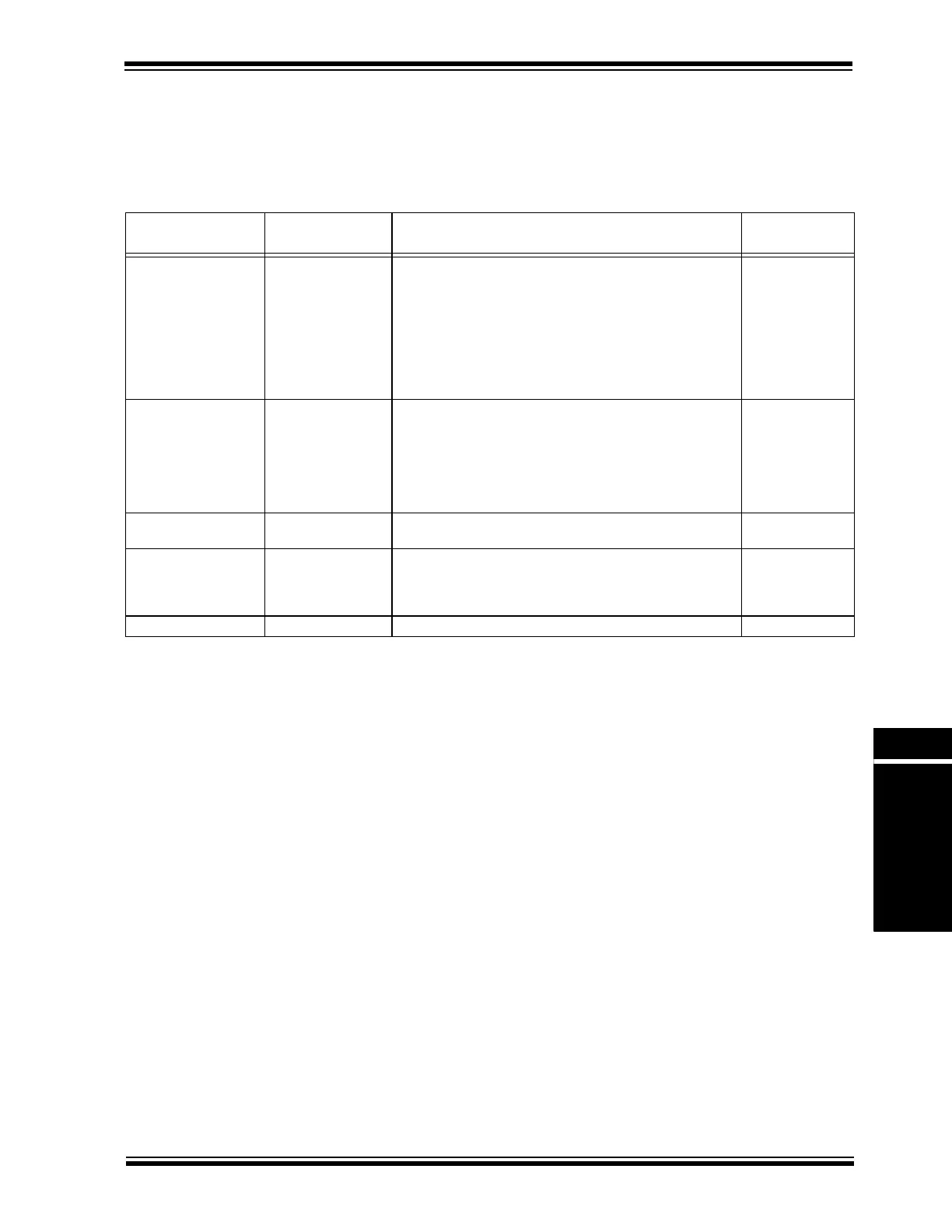
14.3.2.3 Special Cases for Dual Compare Mode Generating a Single Output Pulse
Depending on the relationship of the OCxR, OCxRS and PRy values, the output compare module
has a few unique conditions which should be understood. These special conditions are specified
in Table 14-1, along with the resulting behavior of the module.
Table 14-1: Special Cases for Dual Compare Mode Generating a Single Output Pulse
SFR Logical
Relationship
Special Conditions Operation
Output
at OCx
PRy >= OCxRS and
OCxRS > OCxR
OCxR = 0
Initialize TMRy = 0
In the first iteration of the TMRy counting from 0x0000 up to
PRy, the OCx pin remains low, no pulse is generated. After the
TMRy resets to zero (on period match), the OCx pin goes high
due to match with OCxR. Upon the next TMRy to OCxRS
match, the OCx pin goes low and remains there. The OCxIF
bit will be set as a result of the second compare.
There are two alternative initial conditions to consider:
a] Initialize TMRy = 0 and set OCxR >= 1
b] Initialize TMRy = PRy (PRy > 0) and set OCxR = 0
Pulse will be
delayed by the
value in the PRy
register
depending on
setup
PRy >= OCxR and
OCxR >= OCxRS
OCxR >= 1 and
PRy >= 1
TMRy counts up to OCxR and on a compare match event (i.e.,
TMRy = OCxR), the OCx pin is driven to a high state. TMRy
then continues to count and eventually resets on period match
(i.e., PRy =TMRy). The timer then restarts from 0x0000 and
counts up to OCxRS, and on a compare match event (i.e.,
TMRy = OCxRS), the OCx pin is driven to a low state. The
OCxIF bit will be set as a result of the second compare.
Pulse
OCxRS > PRy and
PRy >= OCxR
None Only the rising edge will be generated at the OCx pin. The
OCxIF will not be set.
Rising edge/
transition to high
OCxR = OCxRS =
PRy = 0x0000
None An output pulse delayed 2 instruction clock periods upon the
match of the timer and period register is generated at the OCx
pin. The OCxIF bit will be set as a result of the second
compare.
Delayed pulse
OCxR > PRy None Unsupported mode, timer resets prior to match condition. Remains low
Note 1: In all the cases considered herein, the TMRy register is assumed to be initialized to 0x0000.
2: OCxR = Compare Register, OCxRS = Secondary Compare Register, TMRy = Timery Count,
PRy = Timery Period Register.