354 FUEL SYSTEM
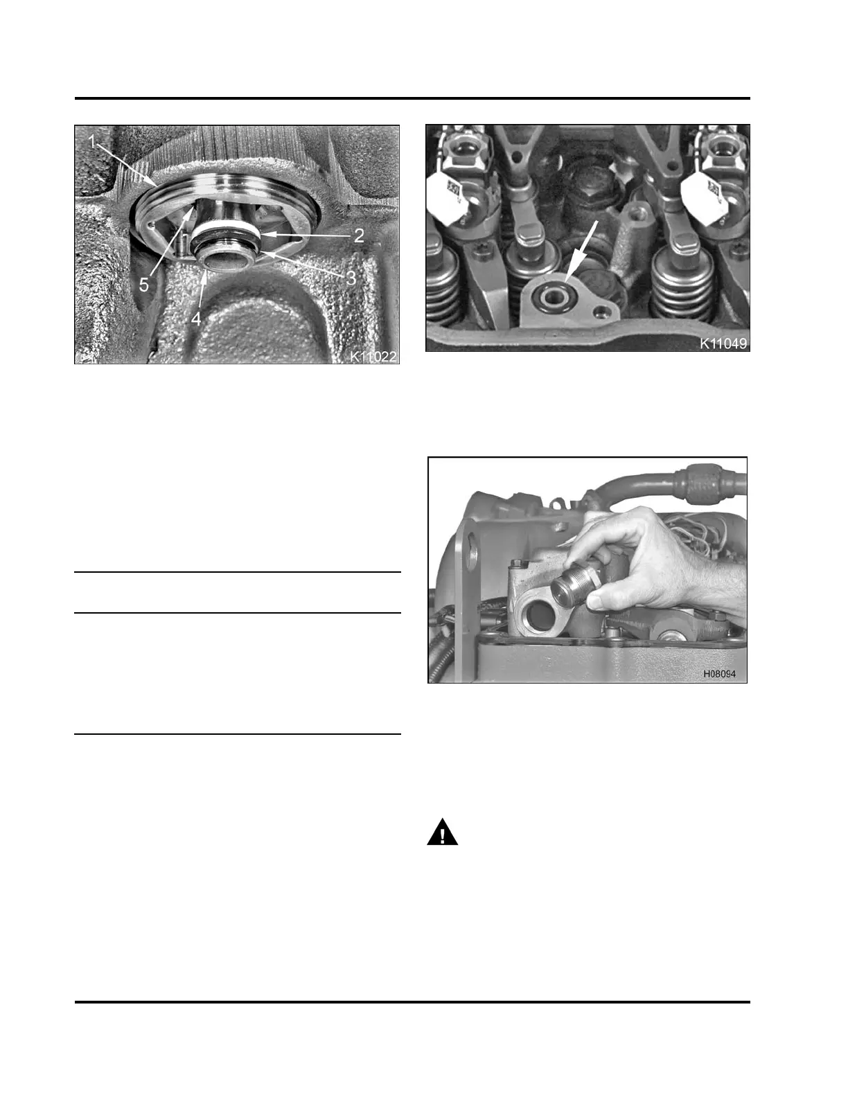
Figure 557 Injector oil inlet adapter installed in
high-pressure oil rail
1. Injector oil inlet adaptor
2. Backup ring
3. Injector oil inlet seal
4. Oil inlet tube
5. Internal O-ring (not serviceable)
Table45 GrooveMeasurement(M)inOilInlet
Tube and Required Backup Ring
Groov e (M) in Oil Inlet
Tube
Backup Ring
5.080 mm (0.200 in)
Backup ring 1.8 mm
(0.07 in)
4.877 mm (0.192 in)
Backup ring 1.6 mm
(0.06 in)
4.420 mm (0.174 in)
Backup ring 1.1 mm
(0.04 in)
3. Install a new backup ring onto injector oil inlet
tubes, according to the groove measurements
listed in the table.
4. Install new injector inlet seal onto injector oil inlet
tubes.
5. Coat backup rings and injector oil inlet seals with
clean engine oil.
Figure 558 Oil inlet O-ring
6. Coat new oil inlet O-ring with clean engine oil and
install O-ring in recess in cylinder head.
Figure 559 Rail end plug assembly
7. See (TSI-05-12-28 New High-pressure Oil Rails,
page 465). If rail end plugs or attenuators were
removed, install new plugs or attenuators and
tighten to the special torque (Table 47).
WARNING: To prevent personal injury or
death, get assistance to remove and install the
high-pressure oil rail assembly.
EGES-265-2
Read all safety instructions in the "Safety Information" section of this manual before doing any procedures.
Follow all warnings, cautions, and notes.
© 2009 Navistar, Inc.
 Loading...


