Remote Control
R&S
®
ESR
1033User Manual 1175.7068.02 ─ 12
Program
:TRACe1:IQ ON
Trace:iq:set NORM,0,32000000,IFP,POS,0,128000
:TRIGger1:SEQuence:LEVel:IFPower -20
:TRACe1:IQ:EGATe ON
:TRACe1:IQ:EGATe:TYPE LEVel
Result
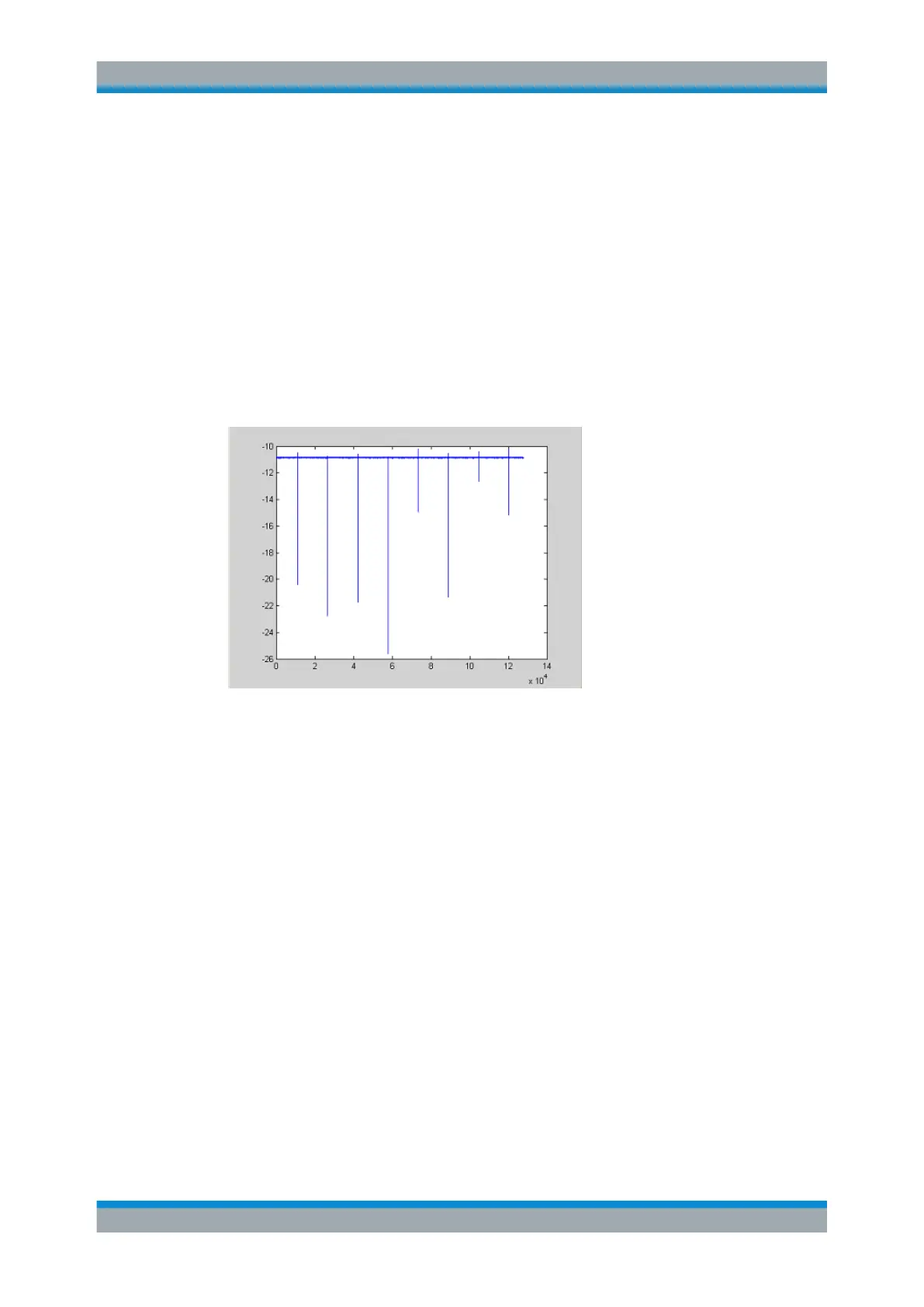
In Figure 11-9, the recorded signal using IQ gating in level mode is displayed. Edges
are only visible around the IFP trigger point, otherwise only the signal level is recorded.
Figure 11-9: Recorded signal using IQ gating in level mode
Measurement example: Edge mode
In edge mode, the gate area is defined by:
●
delay (pretrigger samples)
●
length
●
number of periods
●
gap between the periods
The gate starting point can be defined using an IFP or external trigger.
The Figure 11-10 shows the signal to be recorded in IQ mode.
Remote Control – Programming Examples

 Loading...