Receiver Mode
R&S
®
ESR
183User Manual 1175.7068.02 ─ 12
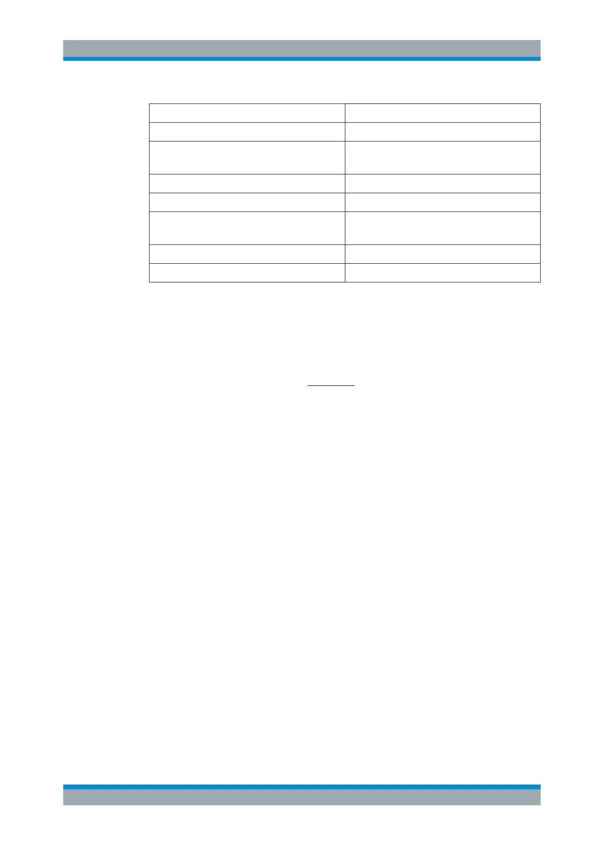
Unit Relative unit
dBµV dBµV/MHz
dBµV/m dBµV/mMHz
(Available for active transducers only.)
dBmV dBmV/MHz
dBµA dBµA/MHz
dBµA/m dBµA/mMHz
(Available for active transducers only.)
dBpW dBpW/MHz
dBpT dBpT/MHz
The conversion to 1 MHz bandwidth is realized via the pulse bandwidth of the selected
resolution bandwidth.
Example:
Conversion example for dbµV:
MHz 1
[MHz]B
log20P[dBµV]]P[dBµV/MHz
imp
P
= Displayed level
B
imp
= Pulse bandwidth of the selected RBW
If you are using another unit, replace "dBµV" with the corresponding unit.
The conversion is also possible when a transducer defines the used unit.
Remote command:
CALCulate<n>:UNIT:POWer on page 667
Grid Range / Grid Min Level
Defines the scale of the vertical diagram axis.
The display ranges go from 10 to 200 dB in 10-dB steps. Invalid entries are rounded off
to the nearest valid value.
"Grid Range"
Defines the level display range for the scan diagram.
"Grid Min
Level"
Defines the minimum level of the display range.
Remote command:
Defining the range of the grid:
DISPlay[:WINDow<n>]:TRACe<t>:Y[:SCALe] on page 844
Defining the minimum level displayed on the axis:
DISPlay[:WINDow<n>]:TRACe<t>:Y[:SCALe]:BOTTom on page 667
Common Measurement Settings

 Loading...

