Quick Start
R&S
®
ESR
68User Manual 1175.7068.02 ─ 12
square brackets after the index indicates the trace to which the marker is assigned.
(Example: M1[1] defines marker 1 on trace 1.) For more than 2 markers, a separate
marker table is displayed beneath the diagram.
The marker function information is not available in realtime mode.
If applicable, the active measurement function for the marker and its main results are
indicated, as well. The functions are indicated with the following abbreviations:
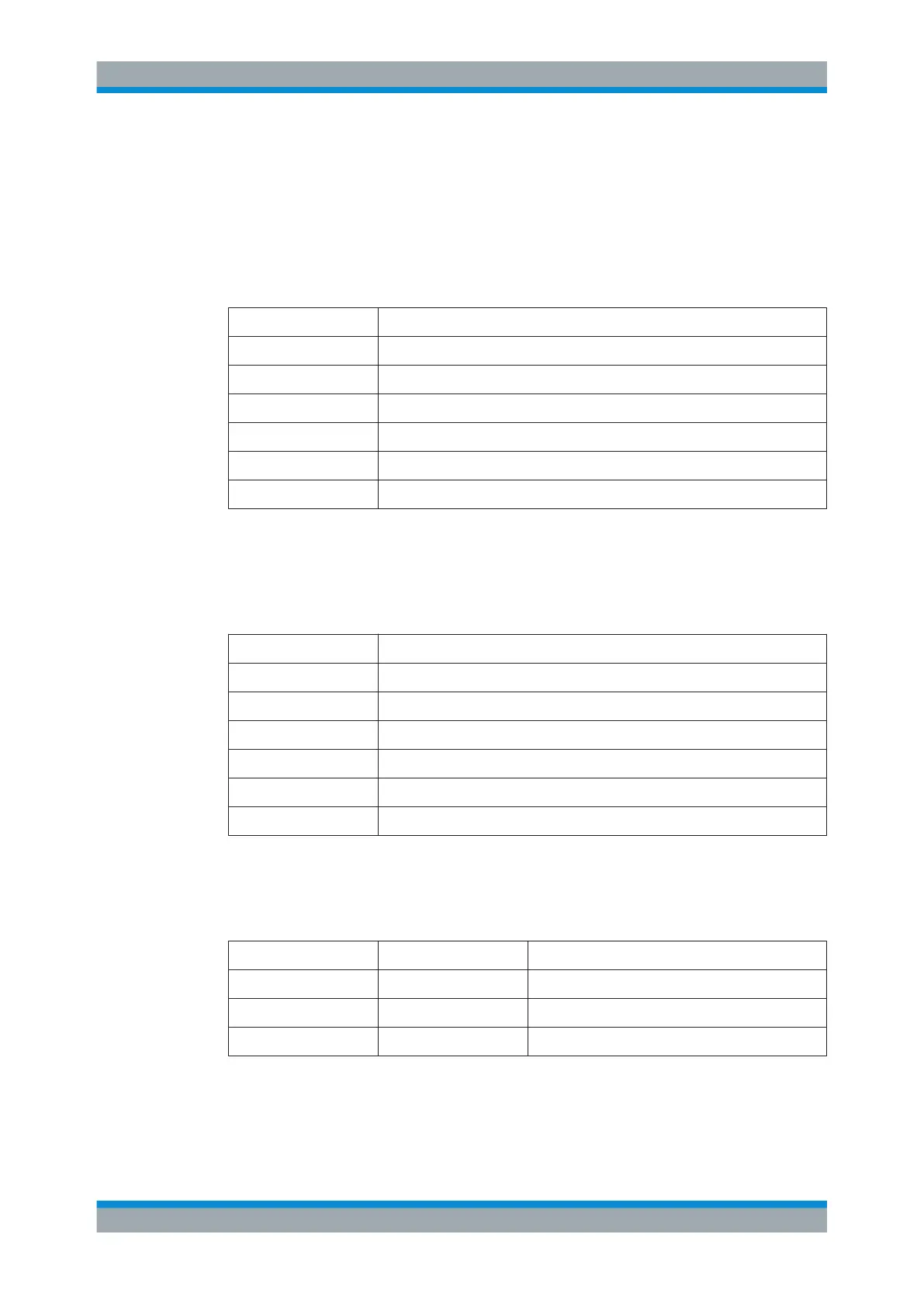
FXD Reference fixed marker active
PHNoise Phase noise measurement active
CNT Frequency counter active
TRK Signal track active
NOIse Noise measurement active
MDepth Measurement of the AM modulation depth active
TOI TOI measurement active
Marker Information in Marker Table
In addition to the marker information displayed within the diagram grid, a separate
marker table may be displayed beneath the diagram. This table provides the following
information for all active markers:
Type Marker type: N (normal), D (delta), T (temporary, internal), PWR (power sensor)
Dgr Diagram number
Trc Trace to which the marker is assigned
Stimulus x-value of the marker
Response y-value of the marker
Func Activated marker or measurement function
Func .Result Result of the active marker or measurement function
Mode-dependant Information in Diagram Footer
The diagram footer (beneath the diagram) contains the following information, depend-
ing on the current mode:
Mode Label Information
FREQ CF Center frequency (between start and stop)
Span Frequency span
SPAN CF (1.0 ms/) Zero span
For most modes, the number of sweep points shown in the display are indicated in the
diagram footer. In zoom mode, the (rounded) number of currently displayed points are
indicated.
Basic Operations

 Loading...

