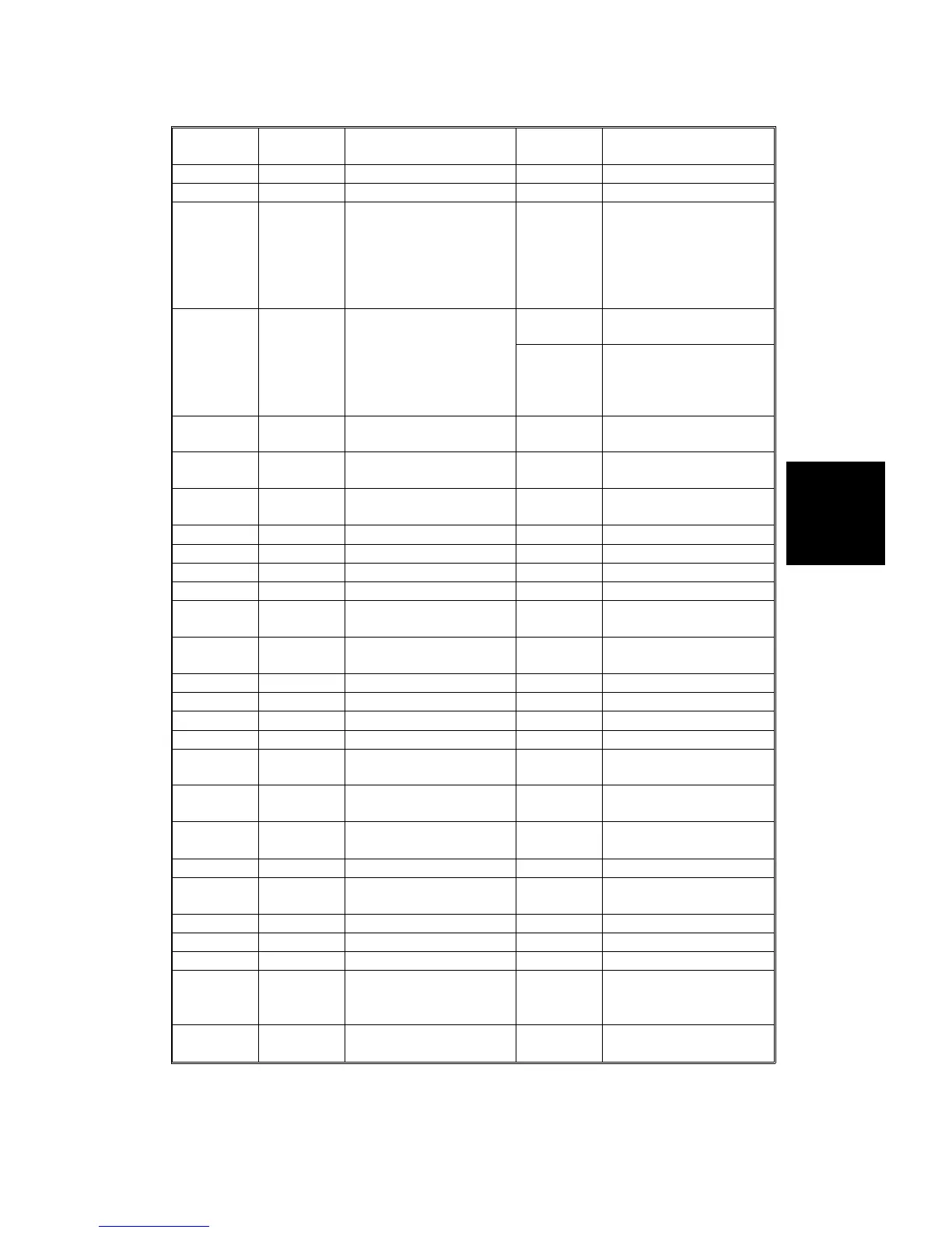
No. Signal Description
Stand-by
(V)
Note
TP214 *INT_BLT Belt H.P. sensor output 0 to 5.0 V
TP215 FB_DAC Not used
TP216 FB_DDC
Feed back data from the
high voltage supply
board: DDC
2.381
±
0.14 V
When the paper transfer
charge unit (casing) is
applied with –2.5 kV, this
value will be measured
with the resistance 100
k
Ω
.
TP217 P_SEN
ID sensor output
0 to 0.1 V
When the machine is in
stand-by mode.
0 to 4.5 V
When the ID sensor
detects the sensor
pattern for the toner
supply control.
TP218 BNK_RXD
Recieved serial data
from the paper tray unit
0 to 5.0 V
TP219 BNK_TXD
Transmition serial data
to the paper tray unit
0 to 5.0 V
TP220 SS_TXD
Transmition serial data
to the sorter stapler
0 to 5.0 V
TP221 *RESET Reset signal 0.2 to 4.8 V Active Low
TP222 *WAIT Wait signal 0 to 5.0 V Active Low
TP223 *WR_FIF Writing signal to FIFO 0 to 5.0 V Active Low
TP224 *FULL FIFO status signal: FULL 0 to 5.0 V Active Low
TP225 *EMPTY
FIFO status signal:
EMPTY
0 to 5.0 V
Active Low
TP226 SCU_TXD
Transmition serial siganl
to the SCU
0 to 5.0 V
TP227 LTRIM Line trimming 0 to 5.0 V
TP228 FGATE Frame gate 0 to 5.0 V
TP229 LGATE Line gate 0 to 5.0 V
TP230 LEVEL LD output level 0 to 5.0 V
TP231 PMCLK
Polygon motor
syncronized clock signal
0 to 5.0 V
TP232 LDCLK
LD drive synchronized
signal
0 to 5.0 V
TP233 DETP2
Laser syncronized
detector board-2: Output
0 to 5.0 V
TP234 FMRCLK Feald memory read clock 0 to 5.0 V
TP235 *DACKS
SCSI controller: DMA
Acknowledge
0 to 5.0 V
Active Low
TP236 *ACK_SC SCSI: *ACK 0 to 5.0 V Active Low
TP237 *INT_SCSI SCSI controller: Interrupt 0 to 5.0 V Active Low
TP238 GND Ground
TP239 PM
Laser syncronized
detector board-1: Main
scan syncronized singal
0 to 5.0 V
TP240 DETP1
Laser syncronized
detector board-1: Output
0 to 5.0 V
Service
Tables
TP/FUSE/LED/SW
SM 4-31 A166/A187/A189