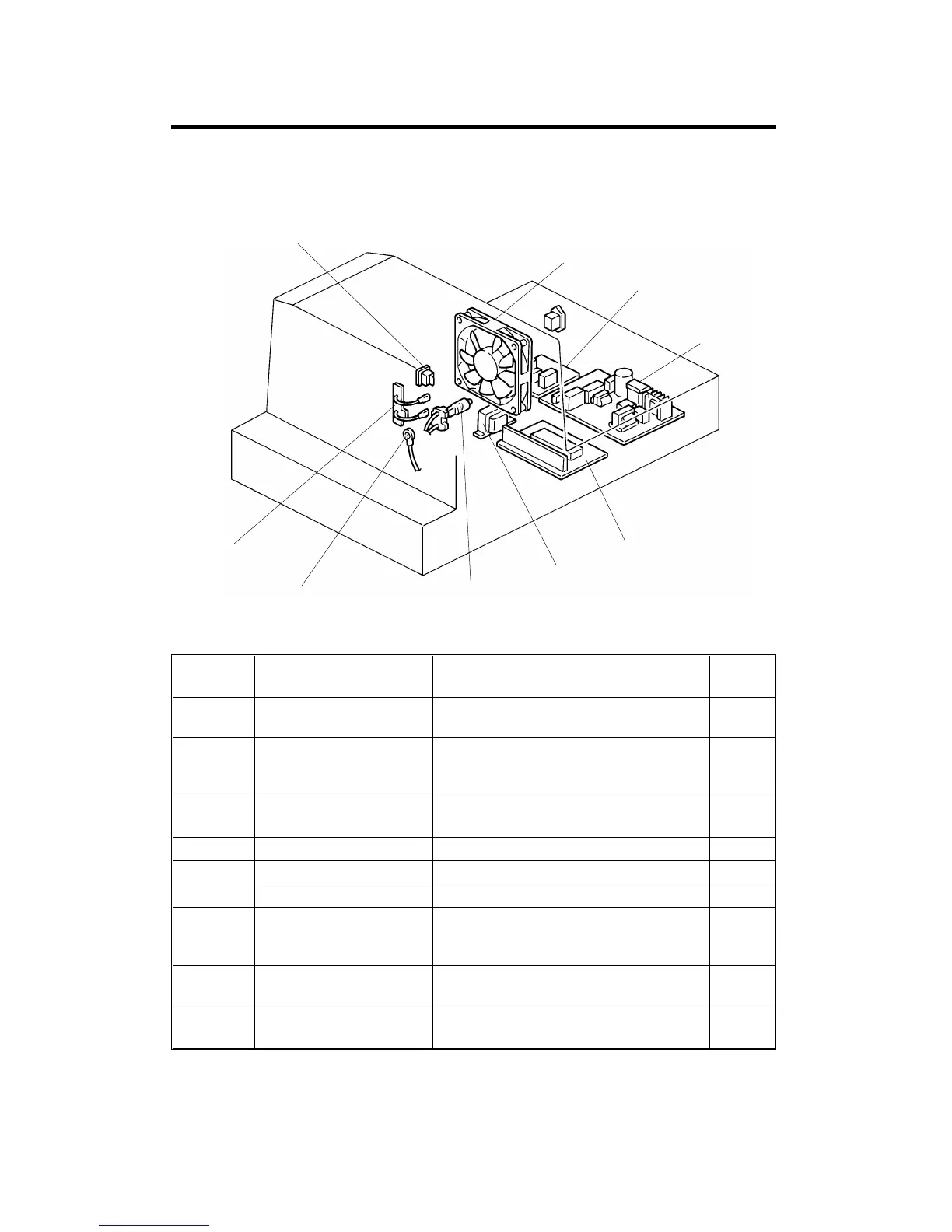
2. ELECTRICAL COMPONENT LAYOUT AND
DESCRIPTIONS
Symbol Name Function
Index
No.
PCB1
Projector Lamp Regulator Supplies dc voltage to the projector lamp
and lamp cooling fan.
4
PCB2
Projector Control Board Controls the projector unit,
communicating with the copier main
board.
5
PCB3
Noise Filter Board
(220–240V machine only)
Removes electrical noise.
3
M1 Lamp Cooling Fan Draws air to the projector lamp section. 2
SW1 Projector Switch Provides power to the projector unit. 1
L1 Projector Lamp Applies light to the film for exposure. 7
TH1
Lamp Thermistor Detects the temperature around the
projector lamp to control the lamp
cooling fan.
8
TF1
Lamp Thermofuse Opens the projector lamp circuit if the
projector lamp section overheats.
9
TR1
Transformer
Steps down the wall voltage to 17
∼
18 V
AC.
6
1
2
3
4
8
7
5
6
9
ELECTRICAL COMPONENT LAYOUT AND DESCRIPTIONS
A166/A187/A189 10-2 SM