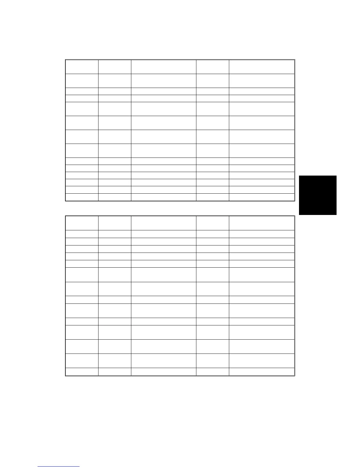
I/O Board 1
No. Signal Description
Stand-by
(V)
Note
TP251 TH
Temperature sensor
output
1.0 to 4.0
If maintaining 0 V or
5 V: NG
TP252 RH Humidity sensor output 1.0 to 4.0
TP253 ANGND Ground
TP254 S_IN
Serial Data (for output)
0 to 5.0
If maintaining 0 V or
5 V: NG
TP255 DE
Data enable signal (for
output)
0 to 5.0
TP256 LE
Latch enable signal (for
Input)
0 to 5.0
If maintaining 0 V or
5 V: NG
TP257 LOAD
Sift/Load signal (for
Input)
0 to 5.0
TP258 CLK1 Clock for output interface 0 to 5.0
TP259 CLEAR Clear signal (for input) 0 to 5.0
TP260 DATA1 Input interface data 1 0 to 5.0
TP261 DATA2 Input interface data 2 0 to 5.0
TP262 GND Ground
TP263 GND Ground
I/O Board 2
No. Signal Description
Stand-by
(V)
Note
TP301 GND Ground
TP302 A+ 0 to 5.0
TP303 A– 0 to 5.0
TP304 B+ 0 to 5.0
TP305 B– 0 to 5.0
TP306 CLK2
Clear signal (for input)
0 to 5.0
If not maintaining
5 V: NG
TP307 DATA2
Input interface data 2
0 to 5.0
If maintaining 0 V or
5 V: NG
TP308 DATA1 Input interface data 1 0 to 5.0
TP309 LOAD
Sift/Load signal (for
Input)
0 to 5.0
TP310 CLK1 Clock for output interface 0 to 5.0
TP311 LE
Latch enable signal (for
output)
0 to 5.0
TP312 DE
Data enable signal (for
output)
0 to 5.0
TP313 S_IN
Serial Data (for output)
0 to 5.0
If maintaining 0 V or
5 V: NG
TP314 GND Ground 0 to 5.0
Service
Tables
TP/FUSE/LED/SW
SM 4-33 A166/A187/A189