3.28
SEL-351A Relay Instruction Manual Date Code 20080213
Overcurrent, Voltage, Synchronism Check, and Frequency Elements
Voltage Elements
Voltage Elements
Enable numerous voltage elements by making the enable setting:
EVOLT = Y
Voltage Values
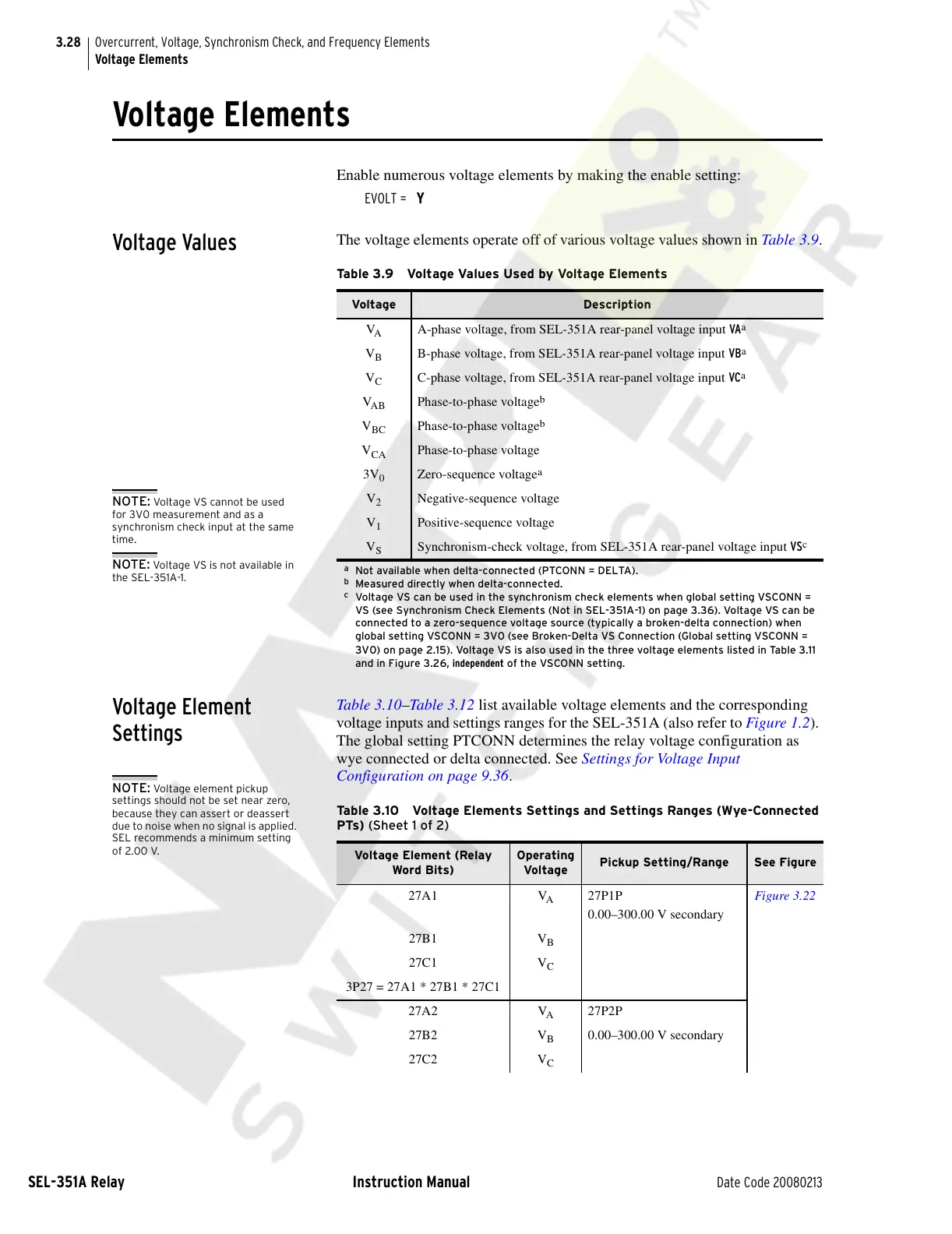
The voltage elements operate off of various voltage values shown in Table 3.9.
Voltage Element
Settings
Table 3.10–Table 3 .12 list available voltage elements and the corresponding
voltage inputs and settings ranges for the SEL-351A (also refer to Figure 1.2).
The global setting PTCONN determines the relay voltage configuration as
wye connected or delta connected. See Settings for Voltage Input
Configuration on page 9.36.
Table 3.9 Voltage Values Used by Voltage Elements
Voltage Description
V
A
A-phase voltage, from SEL-351A rear-panel voltage input VA
a
a
Not available when delta-connected (PTCONN = DELTA).
V
B
B-phase voltage, from SEL-351A rear-panel voltage input VB
a
V
C
C-phase voltage, from SEL-351A rear-panel voltage input VC
a
V
AB
Phase-to-phase voltage
b
b
Measured directly when delta-connected.
V
BC
Phase-to-phase voltage
b
V
CA
Phase-to-phase voltage
3V
0
Zero-sequence voltage
a
V
2
Negative-sequence voltage
V
1
Positive-sequence voltage
V
S
Synchronism-check voltage, from SEL-351A rear-panel voltage input VS
c
c
Voltage VS can be used in the synchronism check elements when global setting VSCONN =
VS (see Synchronism Check Elements (Not in SEL-351A-1) on page 3.36). Voltage VS can be
connected to a zero-sequence voltage source (typically a broken-delta connection) when
global setting VSCONN = 3V0 (see Broken-Delta VS Connection (Global setting VSCONN =
3V0) on page 2.15). Voltage VS is also used in the three voltage elements listed in Table 3.11
and in Figure 3.26, independent of the VSCONN setting.
NOTE: Voltage VS cannot be used
for 3V0 measurement and as a
synchronism check input at the same
time.
NOTE: Voltage VS is not available in
the SEL-351A-1.
Table 3.10 Voltage Elements Settings and Settings Ranges (Wye-Connected
PTs) (Sheet 1 of 2)
Voltage Element (Relay
Word Bits)
Operating
Voltage
Pickup Setting/Range See Figure
27A1 V
A
27P1P
0.00–300.00 V secondary
Figure 3.22
27B1 V
B
27C1 V
C
3P27 = 27A1 * 27B1 * 27C1
27A2 V
A
27P2P
27B2 V
B
0.00–300.00 V secondary
27C2 V
C
NOTE: Voltage element pickup
settings should not be set near zero,
because they can assert or deassert
due to noise when no signal is applied.
SEL recommends a minimum setting
of 2.00 V.
Courtesy of NationalSwitchgear.com