3.17
Date Code 20080213 Instruction Manual SEL-351A Relay
Overcurrent, Voltage, Synchronism Check, and Frequency Elements
Time-Overcurrent Elements
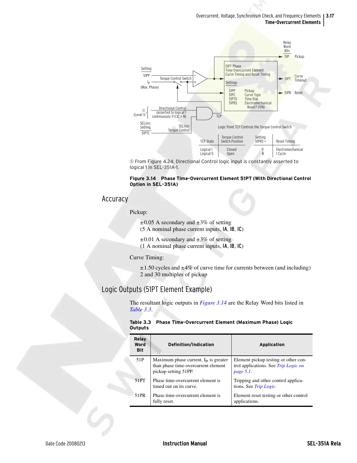
q From Figure 4.24. Directional Control logic input is constantly asserted to
logical 1 in SEL-351A-1.
Figure 3.14 Phase Time-Overcurrent Element 51PT (With Directional Control
Option in SEL-351A)
Accuracy
Pickup:
±0.05 A secondary and ±3% of setting
(5 A nominal phase current inputs, IA, IB, IC)
±0.01 A secondary and ±3% of setting
(1 A nominal phase current inputs, IA, IB, IC)
Curve Timing:
±1.50 cycles and ±4% of curve time for currents between (and including)
2 and 30 multiples of pickup
Logic Outputs (51PT Element Example)
The resultant logic outputs in Figure 3.14 are the Relay Word bits listed in
Table 3.3.
51PP
(Max. Phase)
I
P
Setting
51PTC
Torque Control Switch
Directional Control
(asserted to logical 1
continuously if E32 = N)
q
(Level 1)
SEL
OGIC
Torque Control
51PT Phase
Time-Overcurrent Element
Curve Timing and Reset Timing
Settings
51PP Pickup
51PC Curve Type
51PTD Time Dial
51PRS Electromechanical
Reset? (Y/N)
Pickup
Curve
Timeout
Reset
51P
51PR
51PT
Torque Control
TCP State Switch Position
Logical 1 Closed
Logical 0 Open
Logic Point TCP Controls the Torque Control Switch
Setting
51PRS = Reset Timing
Y Electromechanical
N 1 Cycle
TCP
Relay
Word
Bits
SELOGIC
Setting
Table 3.3 Phase Time-Overcurrent Element (Maximum Phase) Logic
Outputs
Relay
Word
Bit
Definition/Indication Application
51P Maximum phase current, I
P
, is greater
than phase time-overcurrent element
pickup setting 51PP.
Element pickup testing or other con-
trol applications. See Trip Logic on
page 5.1.
51PT Phase time-overcurrent element is
timed out on its curve.
Tripping and other control applica-
tions. See Trip Logic.
51PR Phase time-overcurrent element is
fully reset.
Element reset testing or other control
applications.
Courtesy of NationalSwitchgear.com