9.37
Date Code 20080213 Instruction Manual SEL-351A Relay
Setting the Relay
Settings Explanations
Refer to Voltage Input Configuration (See Settings for Voltage Input
Configuration on page 9.36) on page SET.20.
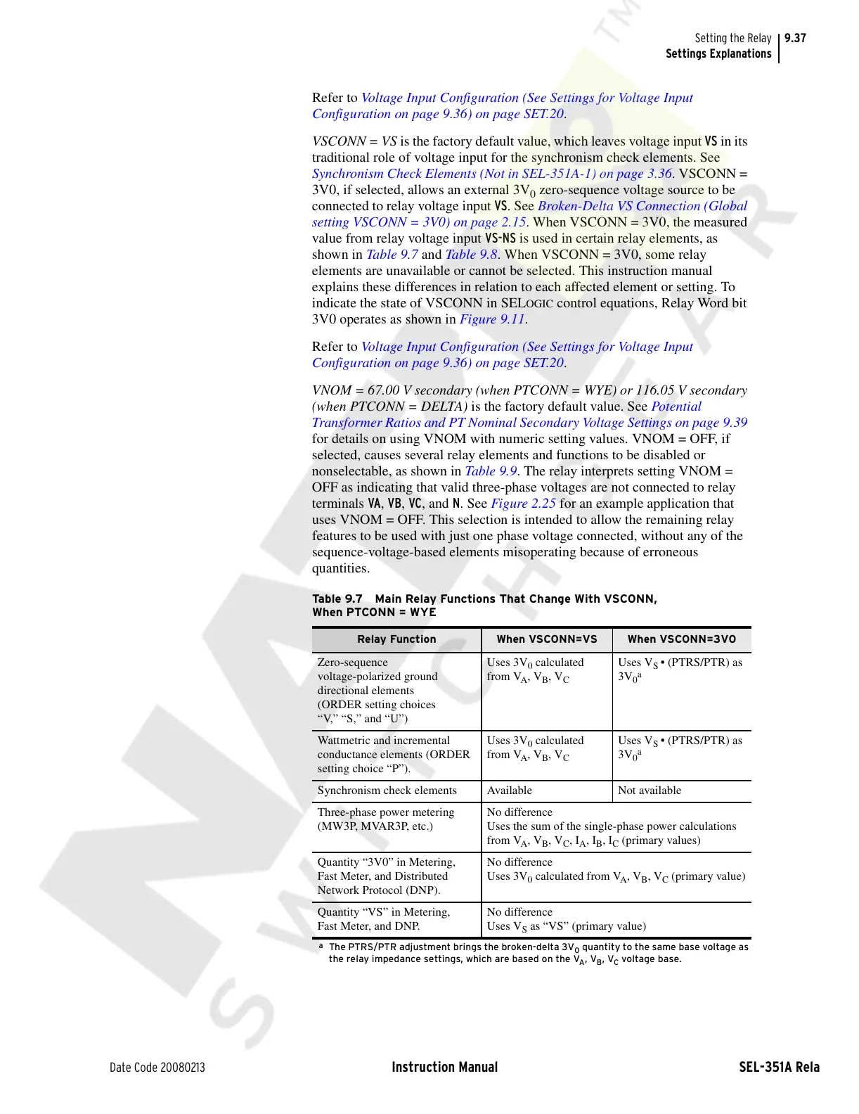
VSCONN = VS is the factory default value, which leaves voltage input VS in its
traditional role of voltage input for the synchronism check elements. See
Synchronism Check Elements (Not in SEL-351A-1) on page 3.36. VSCONN =
3V0, if selected, allows an external 3V
0
zero-sequence voltage source to be
connected to relay voltage input VS. See Broken-Delta VS Connection (Global
setting VSCONN = 3V0) on page 2.15. When VSCONN = 3V0, the measured
value from relay voltage input VS-NS is used in certain relay elements, as
shown in Table 9.7 and Table 9.8. When VSCONN = 3V0, some relay
elements are unavailable or cannot be selected. This instruction manual
explains these differences in relation to each affected element or setting. To
indicate the state of VSCONN in SEL
OGIC control equations, Relay Word bit
3V0 operates as shown in Figure 9.11.
Refer to Voltage Input Configuration (See Settings for Voltage Input
Configuration on page 9.36) on page SET.20.
VNOM = 67.00 V secondary (when PTCONN = WYE) or 116.05 V secondary
(when PTCONN = DELTA) is the factory default value. See Potential
Transformer Ratios and PT Nominal Secondary Voltage Settings on page 9.39
for details on using VNOM with numeric setting values. VNOM = OFF, if
selected, causes several relay elements and functions to be disabled or
nonselectable, as shown in Table 9.9. The relay interprets setting VNOM =
OFF as indicating that valid three-phase voltages are not connected to relay
terminals VA, VB, VC, and N. See Figure 2.25 for an example application that
uses VNOM = OFF. This selection is intended to allow the remaining relay
features to be used with just one phase voltage connected, without any of the
sequence-voltage-based elements misoperating because of erroneous
quantities.
Table 9.7 Main Relay Functions That Change With VSCONN,
When PTCONN = WYE
Relay Function When VSCONN=VS When VSCONN=3V0
Zero-sequence
voltage-polarized ground
directional elements
(ORDER setting choices
“V,” “S,” and “U”)
Uses 3V
0
calculated
from V
A
, V
B
, V
C
Uses V
S
• (PTRS/PTR) as
3V
0
a
a
The PTRS/PTR adjustment brings the broken-delta 3V
0
quantity to the same base voltage as
the relay impedance settings, which are based on the V
A
, V
B
, V
C
voltage base.
Wattmetric and incremental
conductance elements (ORDER
setting choice “P”).
Uses 3V
0
calculated
from V
A
, V
B
, V
C
Uses V
S
• (PTRS/PTR) as
3V
0
a
Synchronism check elements Available Not available
Three-phase power metering
(MW3P, MVAR3P, etc.)
No difference
Uses the sum of the single-phase power calculations
from V
A
, V
B
, V
C
, I
A
, I
B
, I
C
(primary values)
Quantity “3V0” in Metering,
Fast Meter, and Distributed
Network Protocol (DNP).
No difference
Uses 3V
0
calculated from V
A
, V
B
, V
C
(primary value)
Quantity “VS” in Metering,
Fast Meter, and DNP.
No difference
Uses V
S
as “VS” (primary value)
Courtesy of NationalSwitchgear.com