L.4
SEL-351A Relay Instruction Manual Date Code 20080213
SEL Synchrophasors
External Equipment Compensation
External Equipment Compensation
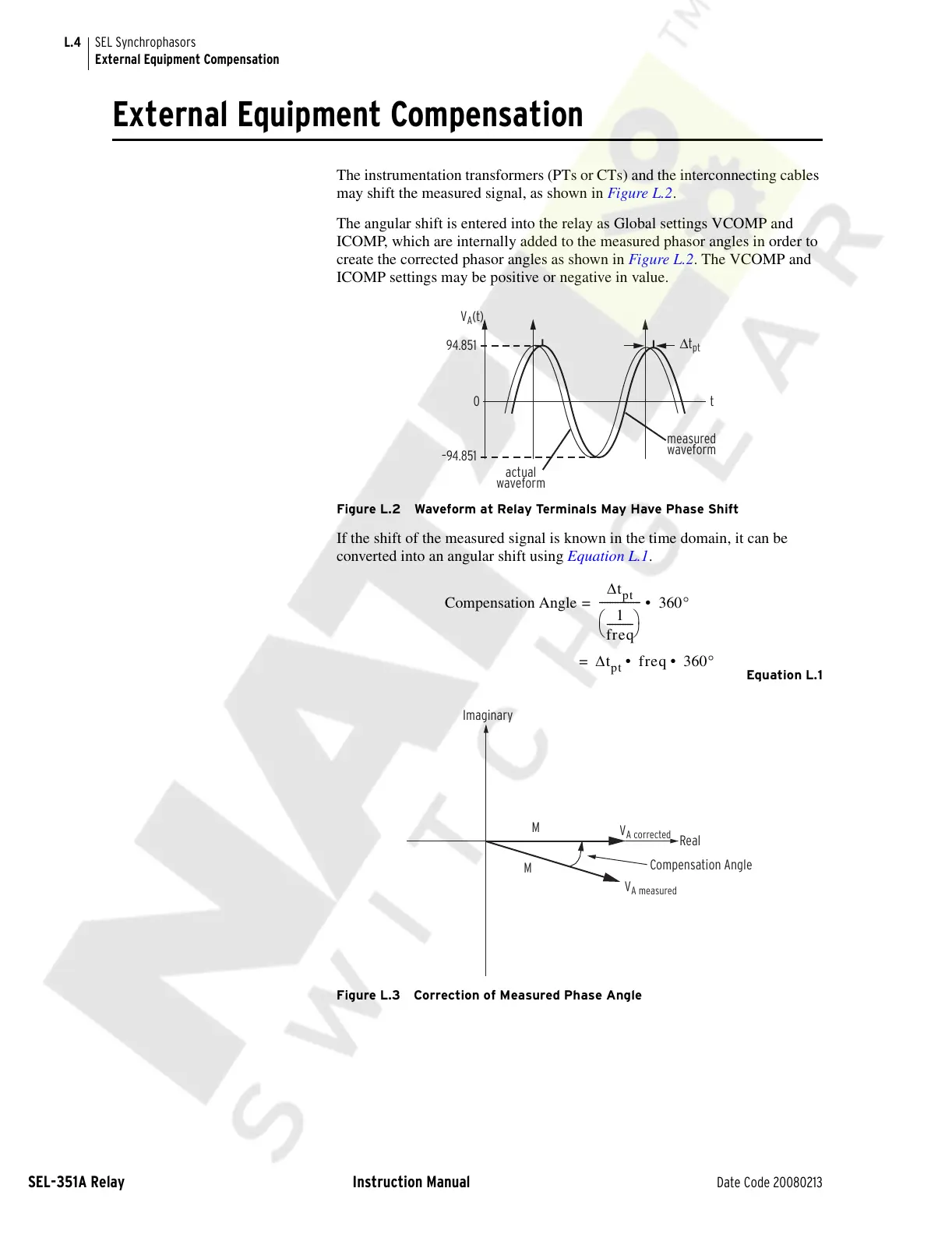
The instrumentation transformers (PTs or CTs) and the interconnecting cables
may shift the measured signal, as shown in Figure L.2.
The angular shift is entered into the relay as Global settings VCOMP and
ICOMP, which are internally added to the measured phasor angles in order to
create the corrected phasor angles as shown in Figure L.2. The VCOMP and
ICOMP settings may be positive or negative in value.
Figure L.2 Waveform at Relay Terminals May Have Phase Shift
If the shift of the measured signal is known in the time domain, it can be
converted into an angular shift using Equation L.1.
Equation L.1
Figure L.3 Correction of Measured Phase Angle
94.851
–94.851
Δt
pt
0t
V
A
(t)
measured
waveform
actual
waveform
Compensation Angle
Δt
pt
1
freq
----------
⎝⎠
⎛⎞
----------------
360°• =
Δt
pt
freq 360°• • =
Imaginary
Real
M
M
V
A measured
V
A corrected
Compensation Angle
Courtesy of NationalSwitchgear.com