13.9
Date Code 20080213 Instruction Manual SEL-351A Relay
Testing and Troubleshooting
Relay Self-Tests
Relay Self-Tests
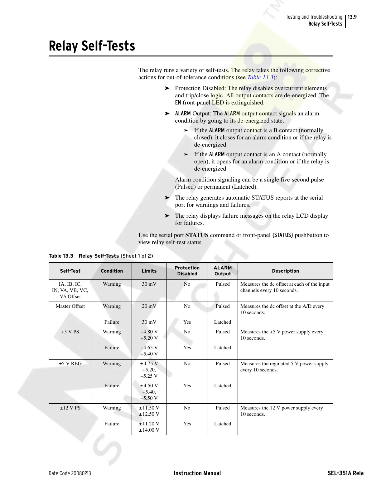
The relay runs a variety of self-tests. The relay takes the following corrective
actions for out-of-tolerance conditions (see Table 13.3):
➤ Protection Disabled: The relay disables overcurrent elements
and trip/close logic. All output contacts are de-energized. The
EN front-panel LED is extinguished.
➤ ALARM Output: The ALARM output contact signals an alarm
condition by going to its de-energized state.
➢ If the ALARM output contact is a B contact (normally
closed), it closes for an alarm condition or if the relay is
de-energized.
➢ If the ALARM output contact is an A contact (normally
open), it opens for an alarm condition or if the relay is
de-energized.
Alarm condition signaling can be a single five-second pulse
(Pulsed) or permanent (Latched).
➤ The relay generates automatic STATUS reports at the serial
port for warnings and failures.
➤ The relay displays failure messages on the relay LCD display
for failures.
Use the serial port STATUS command or front-panel {STATUS} pushbutton to
view relay self-test status.
Table 13.3 Relay Self-Tests (Sheet 1 of 2)
Self-Test Condition Limits
Protection
Disabled
ALARM
Output
Description
IA, IB, IC,
IN, VA, VB, VC,
VS Offset
Warning 30 mV No Pulsed Measures the dc offset at each of the input
channels every 10 seconds.
Master Offset Warning 20 mV No Pulsed Measures the dc offset at the A/D every
10 seconds.
Failure 30 mV Yes Latched
+5 V PS Warning +4.80 V
+5.20 V
No Pulsed Measures the +5 V power supply every
10 seconds.
Failure +4.65 V
+5.40 V
Yes Latched
±5 V REG Warning ±4.75 V
+5.20,
–5.25 V
No Pulsed Measures the regulated 5 V power supply
every 10 seconds.
Failure ±4.50 V
+5.40,
–5.50 V
Yes Latched
±12 V PS Warning ±11.50 V
±12.50 V
No Pulsed Measures the 12 V power supply every
10 seconds.
Failure ±11.20 V
±14.00 V
Yes Latched
Courtesy of NationalSwitchgear.com