F.5
Date Code 20080213 Instruction Manual SEL-351A Relay
Setting Negative-Sequence Overcurrent Elements
Coordinating Negative-Sequence Overcurrent Elements
Apply the Feeder Relay Negative-Sequence Overcurrent Element
(Guideline Step 1 to Guideline Step 3)
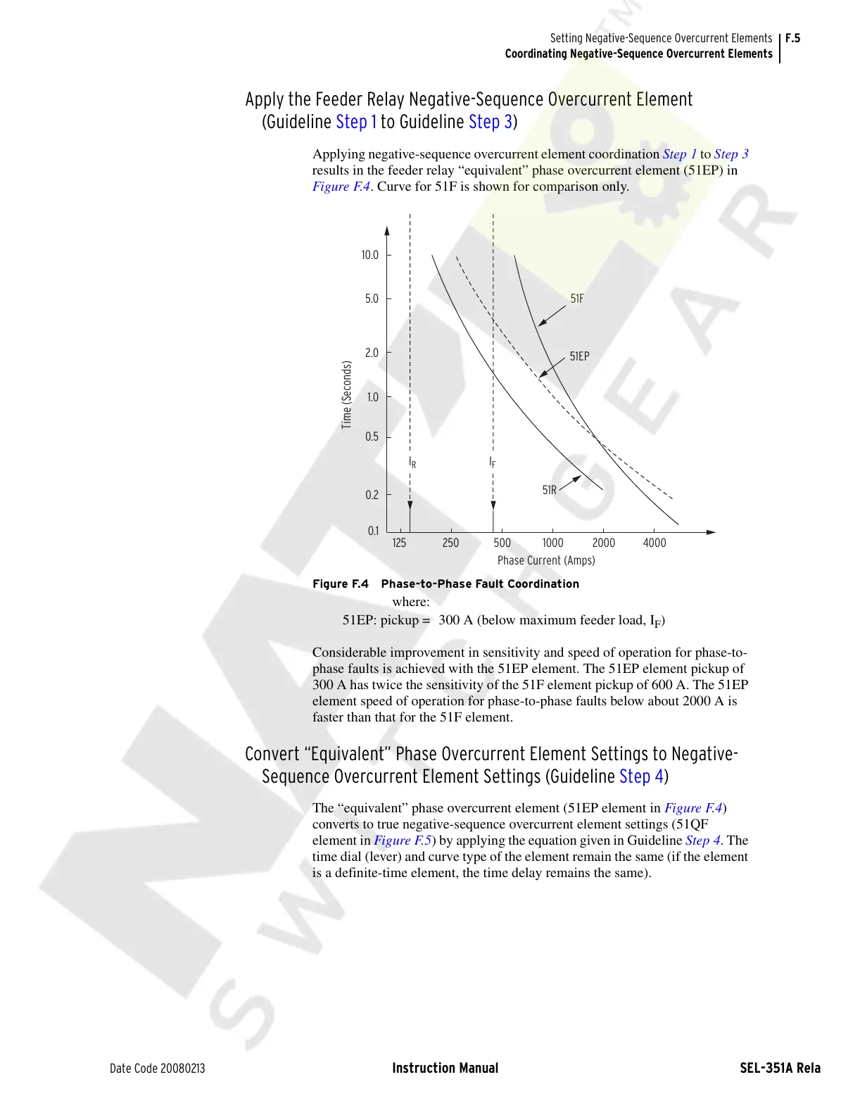
Applying negative-sequence overcurrent element coordination Step 1 to Step 3
results in the feeder relay “equivalent” phase overcurrent element (51EP) in
Figure F.4. Curve for 51F is shown for comparison only.
Figure F.4 Phase-to-Phase Fault Coordination
Considerable improvement in sensitivity and speed of operation for phase-to-
phase faults is achieved with the 51EP element. The 51EP element pickup of
300 A has twice the sensitivity of the 51F element pickup of 600 A. The 51EP
element speed of operation for phase-to-phase faults below about 2000 A is
faster than that for the 51F element.
Convert “Equivalent” Phase Overcurrent Element Settings to Negative-
Sequence Overcurrent Element Settings (Guideline Step 4)
The “equivalent” phase overcurrent element (51EP element in Figure F.4)
converts to true negative-sequence overcurrent element settings (51QF
element in Figure F.5) by applying the equation given in Guideline Step 4. The
time dial (lever) and curve type of the element remain the same (if the element
is a definite-time element, the time delay remains the same).
where:
51EP: pickup = 300 A (below maximum feeder load, I
F
)
Time (Seconds)
10.0
5.0
2.0
1.0
0.5
0.2
0.1
Phase Current (Amps)
125 250 500 1000 2000 4000
51R
51F
I
F
I
R
51EP
Courtesy of NationalSwitchgear.com