4.7
Date Code 20080213 Instruction Manual SEL-351A Relay
Loss-of-Potential, Load Encroachment, and Directional Element Logic
Load-Encroachment Logic (Not in SEL-351A-1)
Again, to provide a margin for setting ZLR:
Equation 4.12
Convert Power Factors to Equivalent Load Angles
The power factor (forward load) can vary from 0.90 lag to 0.95 lead.
Setting PLAF = cos
–1
(0.90) = 26°
Setting NLAF = cos
–1
(0.95) = –18°
The power factor (reverse load) can vary from 0.80 lag to 0.95 lead.
Setting PLAR = 180° – cos
-1
(0.95) = 180° – 18° = 162°
Setting NLAR = 180° + cos
-1
(0.80) = 180° + 37° = 217°
Apply Load-Encroachment Logic to a Phase Time-Overcurrent
Again, from Figure 4.2:
ZLOAD = ZLOUT + ZLIN
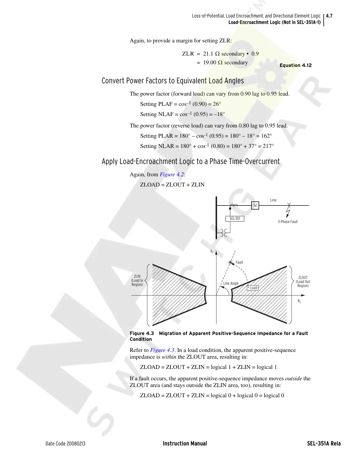
Figure 4.3 Migration of Apparent Positive-Sequence Impedance for a Fault
Condition
Refer to Figure 4.3. In a load condition, the apparent positive-sequence
impedance is within the ZLOUT area, resulting in:
ZLOAD = ZLOUT + ZLIN = logical 1 + ZLIN = logical 1
If a fault occurs, the apparent positive-sequence impedance moves outside the
ZLOUT area (and stays outside the ZLIN area, too), resulting in:
ZLOAD = ZLOUT + ZLIN = logical 0 + logical 0 = logical 0
ZLR 21.1 Ω secondary 0.9• =
19.00 Ω secondary=
X
1
Line Angle
Fault
52
Line
3-Phase Fault
R
1
ZLOUT
(Load Out
Region)
ZLIN
(Load In
Region)
SEL-351
*
Load
Courtesy of NationalSwitchgear.com