3.6
SEL-351A Relay Instruction Manual Date Code 20080213
Overcurrent, Voltage, Synchronism Check, and Frequency Elements
Instantaneous/Definite-Time Overcurrent Elements
Input IN105 asserted (67P1TC = IN105 = logical 1):
Then only the corresponding directional control input from Figure 4.24
has to be considered in the control of phase instantaneous/definite-time
overcurrent elements 67P1/67P1T.
If directional control enable setting E32 = N, then phase instantaneous/
definite-time overcurrent elements 67P1/67P1T are enabled and
nondirectional.
Sometimes SEL
OGIC control equation torque control settings are set to
provide directional control. See Directional Control Provided by Torque
Control Settings (Not in SEL-351A-1) on page 4.57.
Combined Single-Phase Instantaneous Overcurrent Elements
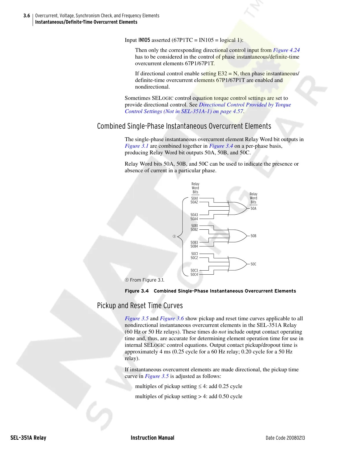
The single-phase instantaneous overcurrent element Relay Word bit outputs in
Figure 3.1 are combined together in Figure 3.4 on a per-phase basis,
producing Relay Word bit outputs 50A, 50B, and 50C.
Relay Word bits 50A, 50B, and 50C can be used to indicate the presence or
absence of current in a particular phase.
q From Figure 3.1.
Figure 3.4 Combined Single-Phase Instantaneous Overcurrent Elements
Pickup and Reset Time Curves
Figure 3.5 and Figure 3.6 show pickup and reset time curves applicable to all
nondirectional instantaneous overcurrent elements in the SEL-351A Relay
(60 Hz or 50 Hz relays). These times do not include output contact operating
time and, thus, are accurate for determining element operation time for use in
internal SEL
OGIC control equations. Output contact pickup/dropout time is
approximately 4 ms (0.25 cycle for a 60 Hz relay; 0.20 cycle for a 50 Hz
relay).
If instantaneous overcurrent elements are made directional, the pickup time
curve in Figure 3.5 is adjusted as follows:
multiples of pickup setting ≤ 4: add 0.25 cycle
multiples of pickup setting > 4: add 0.50 cycle
50A
Relay
Word
Bits
50A1
50A2
50A3
50A4
Relay
Word
Bits
50B
50B1
50B2
50B3
50B4
50C
50C1
50C2
50C3
50C4
q
Courtesy of NationalSwitchgear.com