4.10
SEL-351A Relay Instruction Manual Date Code 20080213
Loss-of-Potential, Load Encroachment, and Directional Element Logic
Directional Control for Neutral-Ground and Residual-Ground Overcurrent Elements (Not in SEL-351A-1)
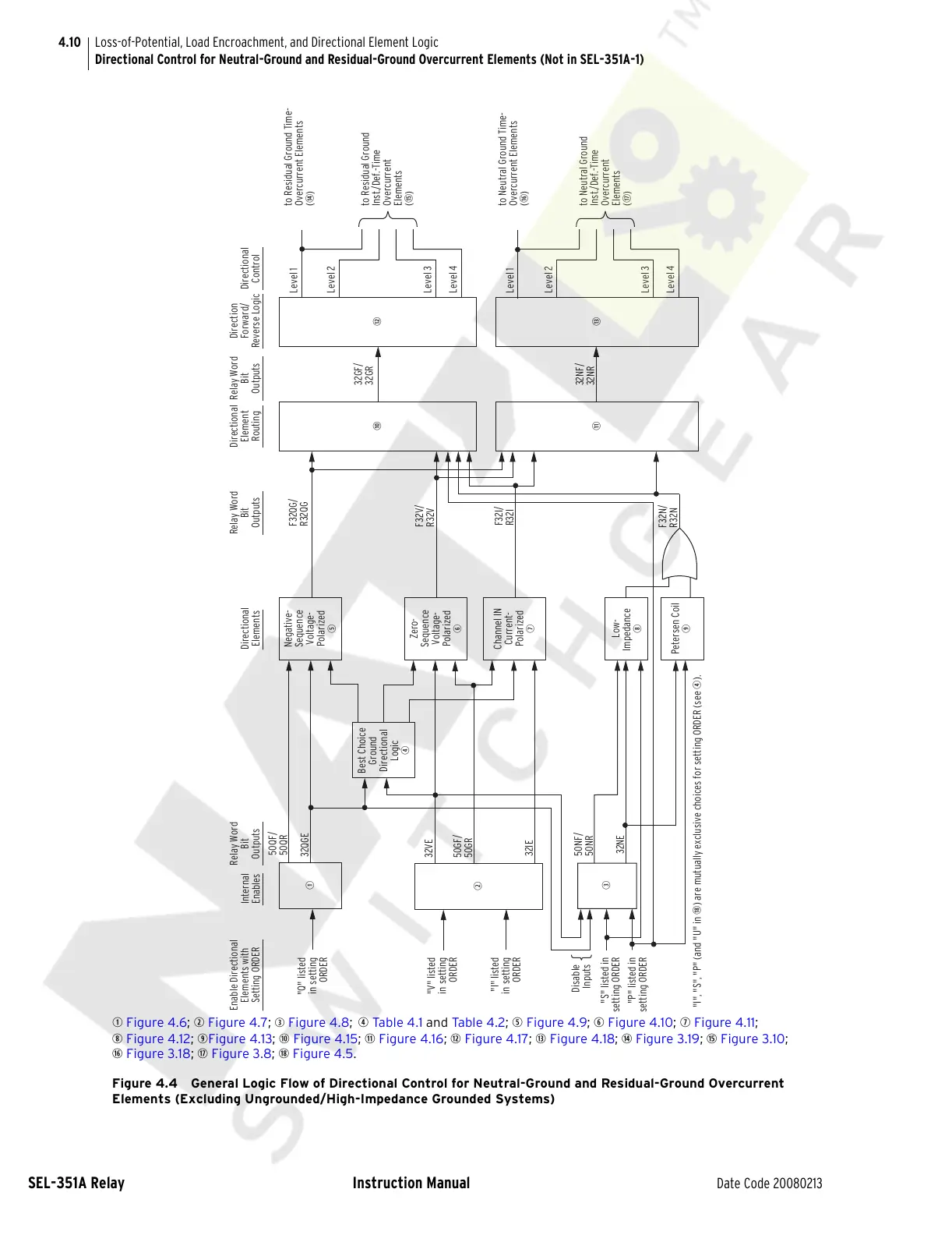
q Figure 4.6; w Figure 4.7; e Figure 4.8; r Tab le 4 .1 and Ta ble 4.2; t Figure 4.9; y Figure 4.10; u Figure 4.11;
i Figure 4.12; oFigure 4.13; a Figure 4.15; s Figure 4.16; d Figure 4.17; f Figure 4.18; g Figure 3.19; h Figure 3.10;
j Figure 3.18; k Figure 3.8; l Figure 4.5.
Figure 4.4 General Logic Flow of Directional Control for Neutral-Ground and Residual-Ground Overcurrent
Elements (Excluding Ungrounded/High-Impedance Grounded Systems)
e
32IE
"I" listed
in setting
ORDER
F32N/
R32N
F32I/
R32I
Channel IN
Current-
Polarized
u
s
f
"I", "S", "P" (and "U" in l) are mutually exclusive choices for setting ORDER (see r).
32NE
50NF/
50NR
Disable
Inputs
Petersen Coil
o
Low-
Impedance
i
to Neutral Ground Time-
Overcurrent Elements
(j)
to Neutral Ground
Inst./Def.-Time
Overcurrent
Elements
(k)
Level 1
Level 2
Level 3
Level 4
32NF/
32NR
Best Choice
Ground
Directional
Logic
r
Zero-
Sequence
Voltage-
Polarized
y
Negative-
Sequence
Voltage-
Polarized
t
q
a
w
32VE
"V" listed
in setting
ORDER
"S" listed in
setting ORDER
"P" listed in
setting ORDER
"Q" listed
in setting
ORDER
32QGE
50QF/
50QR
50GF/
50GR
F32V/
R32V
F32QG/
R32QG
32GF/
32GR
d
Level 1
Level 2
Level 3
Level 4
to Residual Ground
Inst./Def.-Time
Overcurrent
Elements
(h)
to Residual Ground Time-
Overcurrent Elements
(g)
Enable Directional
Elements with
Setting ORDER
Internal
Enables
Relay Word
Bit
Outputs
Directional
Elements
Relay Word
Bit
Outputs
Relay Word
Bit
Outputs
Direction
Forward/
Reverse Logic
Directional
Control
Directional
Element
Routing
Courtesy of NationalSwitchgear.com