4.13
Date Code 20080213 Instruction Manual SEL-351A Relay
Loss-of-Potential, Load Encroachment, and Directional Element Logic
Directional Control for Neutral-Ground and Residual-Ground Overcurrent Elements (Not in SEL-351A-1)
Figure 4.4 and Figure 4.5 give an overview of how these directional elements
are enabled and routed to control the neutral-ground and residual-ground
overcurrent elements.
Note in Figure 4.4 and Figure 4.5 that setting ORDER enables the directional
elements. Setting ORDER can be set with the elements listed and defined in
Table 4.1, subject to the setting combination constraints in Table 4.2. Note that
Table 4.1 and Table 4.2 also list the directional element availability, per model
(according to the neutral channel [IN] rating).
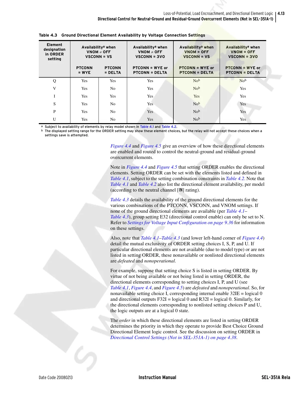
Table 4.3 details the availability of the ground directional elements for the
various combinations of the PTCONN, VSCONN, and VNOM settings. If
none of the ground directional elements are available (per Table 4.1–
Table 4.3), group setting E32 (directional control enable) can only be set to N.
Refer to Settings for Voltage Input Configuration on page 9.36 for information
on these settings.
Also, note that Tabl e 4.1–Table 4 .3 (and lower left-hand corner of Figure 4.4)
detail the mutual exclusivity of ORDER setting choices I, S, P, and U. If
particular directional elements are not available (due to model type) or are not
listed in setting ORDER, these nonavailable or nonlisted directional elements
are defeated and nonoperational.
For example, suppose that setting choice S is listed in setting ORDER. By
virtue of not being available or not being listed in setting ORDER, the
directional elements corresponding to setting choices I, P, and U (see
Table 4.1, Figure 4.4, and Figure 4.5) are defeated and nonoperational. So, for
nonavailable setting choice I, corresponding internal enable 32IE = logical 0
and directional outputs F32I = logical 0 and R32I = logical 0. Similarly, for
the directional elements corresponding to nonlisted setting choices P and U,
the logic outputs are at a logical 0 state.
The order in which these directional elements are listed in setting ORDER
determines the priority in which they operate to provide Best Choice Ground
Directional Element logic control. See the discussion on setting ORDER in
Directional Control Settings (Not in SEL-351A-1) on page 4.38.
Table 4.3 Ground Directional Element Availability by Voltage Connection Settings
Element
designation
in ORDER
setting
Availability
a
when
VNOM ≠ OFF
VSCONN = VS
Availability
a
when
VNOM ≠ OFF
VSCONN = 3V0
Availability
a
when
VNOM = OFF
VSCONN = VS
Availability
a
when
VNOM = OFF
VSCONN = 3V0
PTCONN
= WYE
PTCONN
= DELTA
PTCONN = WYE or
PTCONN = DELTA
PTCONN = WYE or
PTCONN = DELTA
PTCONN = WYE or
PTCONN = DELTA
Q Yes Yes Yes No
b
No
b
VYesNo Yes No
b
Yes
I Yes Yes Yes Yes Yes
SYesNo Yes No
b
Yes
PYesNo Yes No
b
Yes
UYesNo Yes No
b
Yes
a
Subject to availability of elements by relay model shown in Ta b le 4 . 1 and Ta b le 4 . 2.
b
The displayed setting range for the ORDER setting may show these element choices, but the relay will not accept these choices when a
settings save is attempted.
Courtesy of NationalSwitchgear.com


 To Next Page