4.11
Date Code 20080213 Instruction Manual SEL-351A Relay
Loss-of-Potential, Load Encroachment, and Directional Element Logic
Directional Control for Neutral-Ground and Residual-Ground Overcurrent Elements (Not in SEL-351A-1)
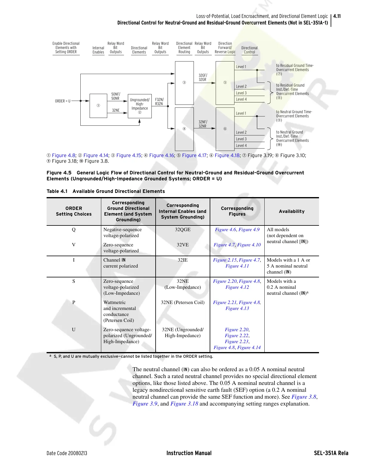
q Figure 4.8; w Figure 4.14; e Figure 4.15; r Figure 4.16; t Figure 4.17; y Figure 4.18; u Figure 3.19; i Figure 3.10;
o Figure 3.18; a Figure 3.8.
Figure 4.5 General Logic Flow of Directional Control for Neutral-Ground and Residual-Ground Overcurrent
Elements (Ungrounded/High-Impedance Grounded Systems; ORDER = U)
The neutral channel (IN) can also be ordered as a 0.05 A nominal neutral
channel. Such a rated neutral channel provides no special directional element
options, like those listed above. The 0.05 A nominal neutral channel is a
legacy nondirectional sensitive earth fault (SEF) option (a 0.2 A nominal
neutral channel can provide the same SEF function and more). See Figure 3.8,
Figure 3.9, and Figure 3.18 and accompanying setting ranges explanation.
q
F32N/
R32N
r
y
32NE
ORDER = U
50NF/
50NR
to Neutral Ground Time-
Overcurrent Elements
(
o
)
to Neutral Ground
Inst./Def.-Time
Overcurrent Elements
(
a
)
Level 1
32NF/
32NR
Ungrounded/
High-
Impedance
w
e
32GF/
32GR
t
Level 1
Level 2
Level 3
Level 4
to Residual Ground
Inst./Def.-Time
Overcurrent Elements
(
i
)
Level 2
Level 3
Level 4
to Residual Ground Time-
Overcurrent Elements
(
u
)
Enable Directional
Elements with
Setting ORDER
Internal
Enables
Relay Word
Bit
Outputs
Directional
Elements
Relay Word
Bit
Outputs
Relay Word
Bit
Outputs
Direction
Forward/
Reverse Logic
Directional
Control
Directional
Element
Routing
Table 4.1 Available Ground Directional Elements
ORDER
Setting Choices
Corresponding
Ground Directional
Element (and System
Grounding)
Corresponding
Internal Enables (and
System Grounding)
Corresponding
Figures
Availability
Q Negative-sequence
voltage-polarized
32QGE Figure 4.6, Figure 4.9 All models
(not dependent on
neutral channel [IN])
V Zero-sequence
voltage-polarized
32VE Figure 4.7, Figure 4.10
I Channel IN
current polarized
32IE Figure 2.15, Figure 4.7,
Figure 4.11
Models with a 1 A or
5 A nominal neutral
channel (IN)
S Zero-sequence
voltage-polarized
(Low-Impedance)
32NE
(Low-Impedance)
Figure 2.20, Figure 4.8,
Figure 4.12
Models with a
0.2 A nominal
neutral channel (IN)
a
P Wattmetric
and incremental
conductance
(Petersen Coil)
32NE (Petersen Coil) Figure 2.21, Figure 4.8,
Figure 4.13
U Zero-sequence voltage-
polarized (Ungrounded/
High-Impedance)
32NE (Ungrounded/
High-Impedance)
Figure 2.20,
Figure 2.22,
Figure 2.23,
Figure 4.8, Figure 4.14
a
S, P, and U are mutually exclusive—cannot be listed together in the ORDER setting.
Courtesy of NationalSwitchgear.com