8.15
Date Code 20080213 Instruction Manual SEL-351A Relay
Breaker Monitor and Metering
Station DC Battery Monitor (Not in SEL-351A-1)
Station DC Battery Monitor (Not in SEL-351A-1)
The station dc battery monitor in the SEL-351A can alarm for under- or
overvoltage dc battery conditions and give a view of how much the station dc
battery voltage dips when tripping, closing, and other dc control functions
take place. The monitor measures the station dc battery voltage applied to the
rear-panel terminals labeled POWER (see Figure 2.2, Figure 2.5, and
Figure 2.6). The station dc battery monitor settings (DCLOP and DCHIP) are
available via the SET G command (see Table 9.1 and also Station DC Battery
Monitor (See Figure 8.9 and Figure 8.10) on page SET.21).
DC Under- and
Overvoltage
Elements
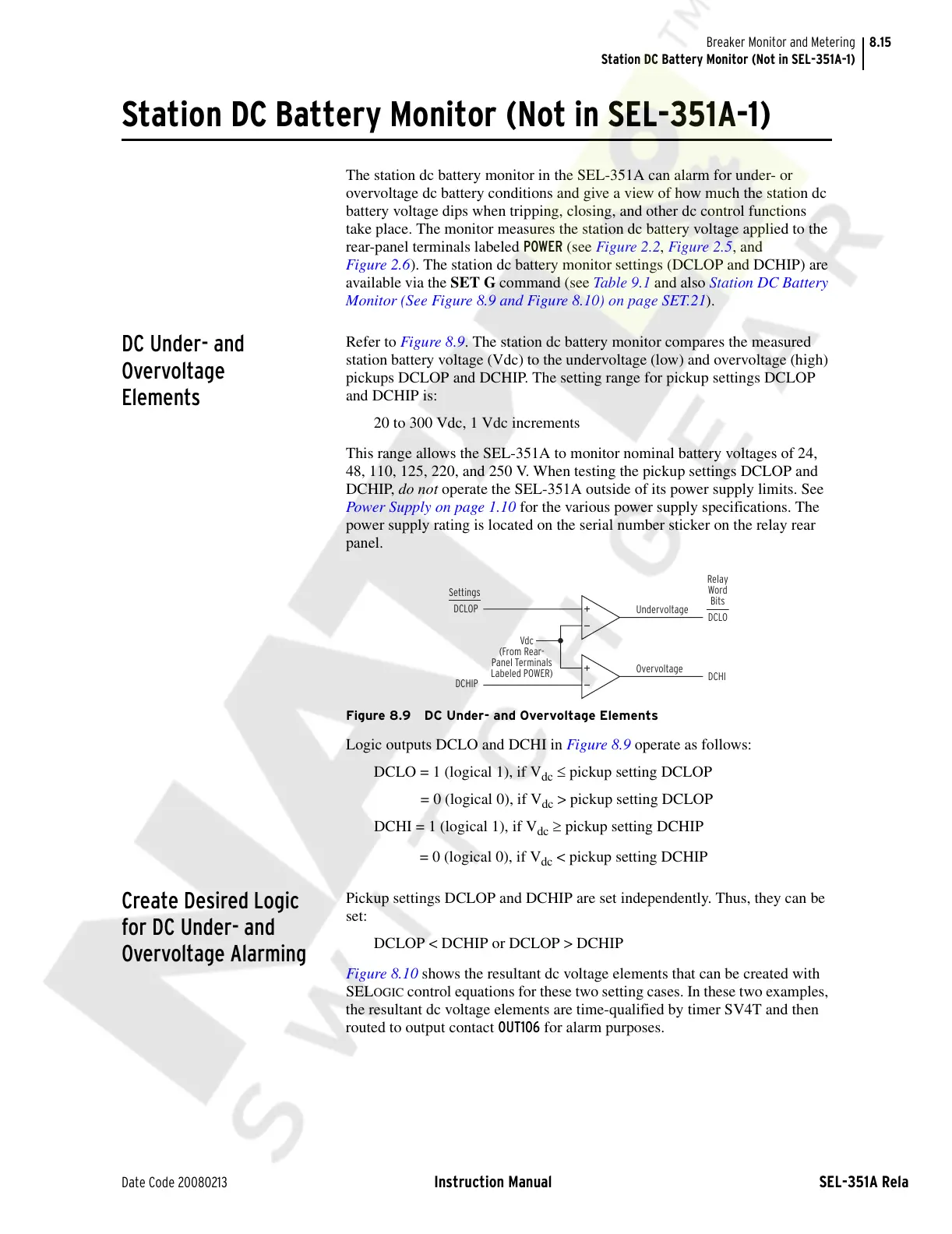
Refer to Figure 8.9. The station dc battery monitor compares the measured
station battery voltage (Vdc) to the undervoltage (low) and overvoltage (high)
pickups DCLOP and DCHIP. The setting range for pickup settings DCLOP
and DCHIP is:
20 to 300 Vdc, 1 Vdc increments
This range allows the SEL-351A to monitor nominal battery voltages of 24,
48, 110, 125, 220, and 250 V. When testing the pickup settings DCLOP and
DCHIP, do not operate the SEL-351A outside of its power supply limits. See
Power Supply on page 1.10 for the various power supply specifications. The
power supply rating is located on the serial number sticker on the relay rear
panel.
Figure 8.9 DC Under- and Overvoltage Elements
Logic outputs DCLO and DCHI in Figure 8.9 operate as follows:
DCLO = 1 (logical 1), if V
dc
≤ pickup setting DCLOP
= 0 (logical 0), if V
dc
> pickup setting DCLOP
DCHI = 1 (logical 1), if V
dc
≥ pickup setting DCHIP
= 0 (logical 0), if V
dc
< pickup setting DCHIP
Create Desired Logic
for DC Under- and
Overvoltage Alarming
Pickup settings DCLOP and DCHIP are set independently. Thus, they can be
set:
DCLOP < DCHIP or DCLOP > DCHIP
Figure 8.10 shows the resultant dc voltage elements that can be created with
SEL
OGIC control equations for these two setting cases. In these two examples,
the resultant dc voltage elements are time-qualified by timer SV4T and then
routed to output contact OUT106 for alarm purposes.
DCLO
DCHI
Vdc
Relay
Word
Bits
DCLOP
DCHIP
Settings
Undervoltage
Overvoltage
(From Rear-
Panel Terminals
Labeled POWER)
Courtesy of NationalSwitchgear.com