7.3
Date Code 20080213 Instruction Manual SEL-351A Relay
Inputs, Outputs, Timers, and Other Control Logic
Optoisolated Inputs
Only a few applications might require input pickup/dropout debounce timers
set less than 1/4 cycle [e.g., if setting IN105D = 0.13, internally the timer runs
at the nearest 1/16 cycle: 2/16 cycles (2/16 = 0.1250)].
The relay processing interval is 1/4 cycle, so Relay Word bits IN101–IN106
are updated every 1/4 cycle. The optoisolated input status may have made it
through the pickup/dropout debounce timer (for settings less than 1/4 cycle)
because these timers run each 1/16 cycle, but Relay Word bits IN101–IN106
are updated every 1/4 cycle.
If more than 1 cycle of debounce is needed, run Relay Word bit INn (n = 1–6)
through a SEL
OGIC control equation variable timer and use the output of the
timer for input functions (see Figure 7.23 and Figure 7.24).
Input Functions
There are no optoisolated input settings such as:
IN101 =
IN102 =
Optoisolated inputs IN101–IN106 receive their function by how their
corresponding Relay Word bits IN101–IN106 are used in SEL
OGIC control
equations.
Factory Settings
Examples
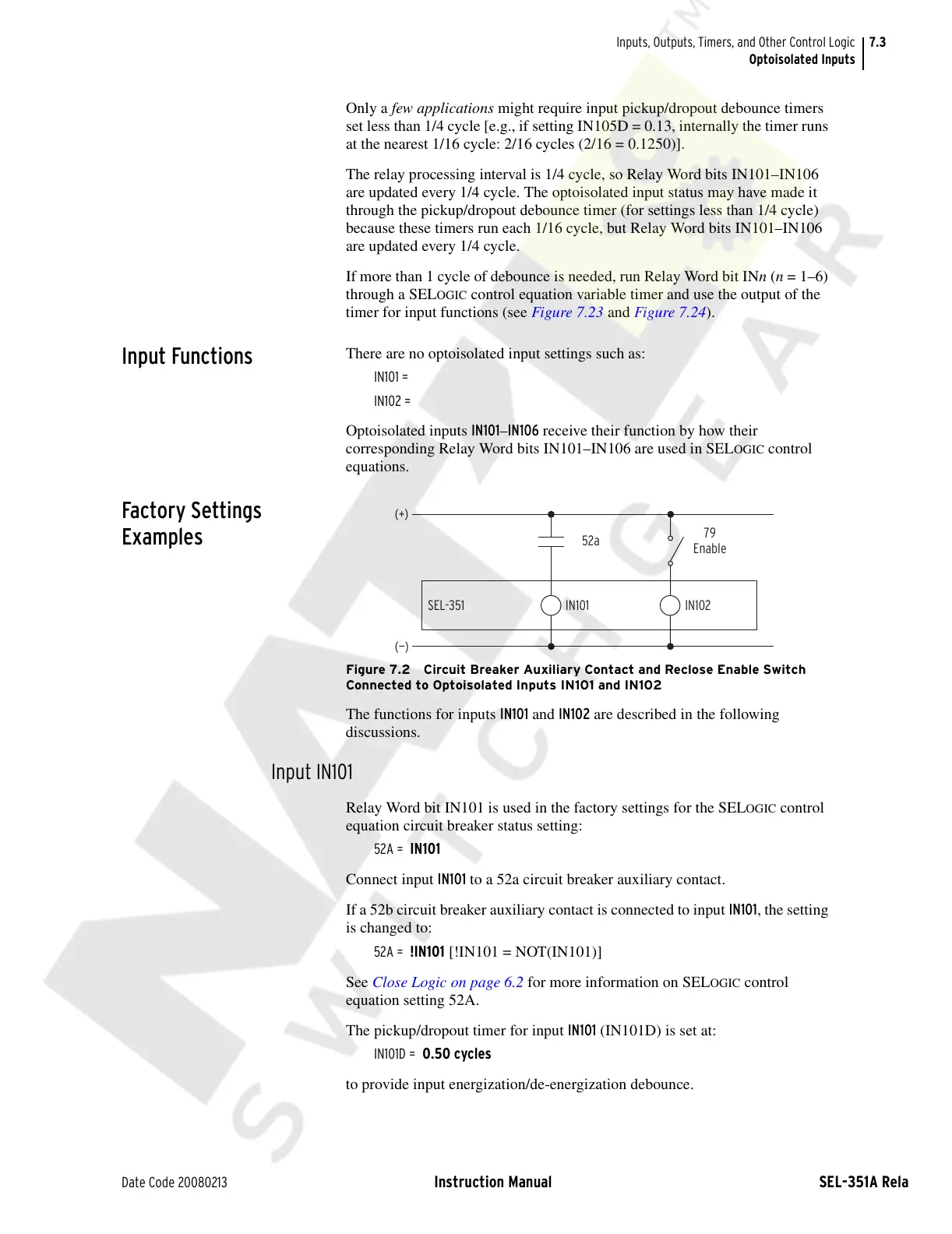
Figure 7.2 Circuit Breaker Auxiliary Contact and Reclose Enable Switch
Connected to Optoisolated Inputs IN101 and IN102
The functions for inputs IN101 and IN102 are described in the following
discussions.
Input IN101
Relay Word bit IN101 is used in the factory settings for the SELOGIC control
equation circuit breaker status setting:
52A = IN101
Connect input IN101 to a 52a circuit breaker auxiliary contact.
If a 52b circuit breaker auxiliary contact is connected to input IN101, the setting
is changed to:
52A = !IN101 [!IN101 = NOT(IN101)]
See Close Logic on page 6.2 for more information on SEL
OGIC control
equation setting 52A.
The pickup/dropout timer for input IN101 (IN101D) is set at:
IN101D = 0.50 cycles
to provide input energization/de-energization debounce.
79
Enable
52a
SEL-351
(+)
IN102
(—)
IN101
Courtesy of NationalSwitchgear.com