7.45
Date Code 20080213 Instruction Manual SEL-351A Relay
Inputs, Outputs, Timers, and Other Control Logic
Rotating Default Display (Only on Models With LCD)
Setting DPn = 0 and using the DPn_0 in the text settings allows the setting to
permanently rotate in the display. The DPn logic equation can be set to control
the text display—turning it on and off under certain conditions. With the relay
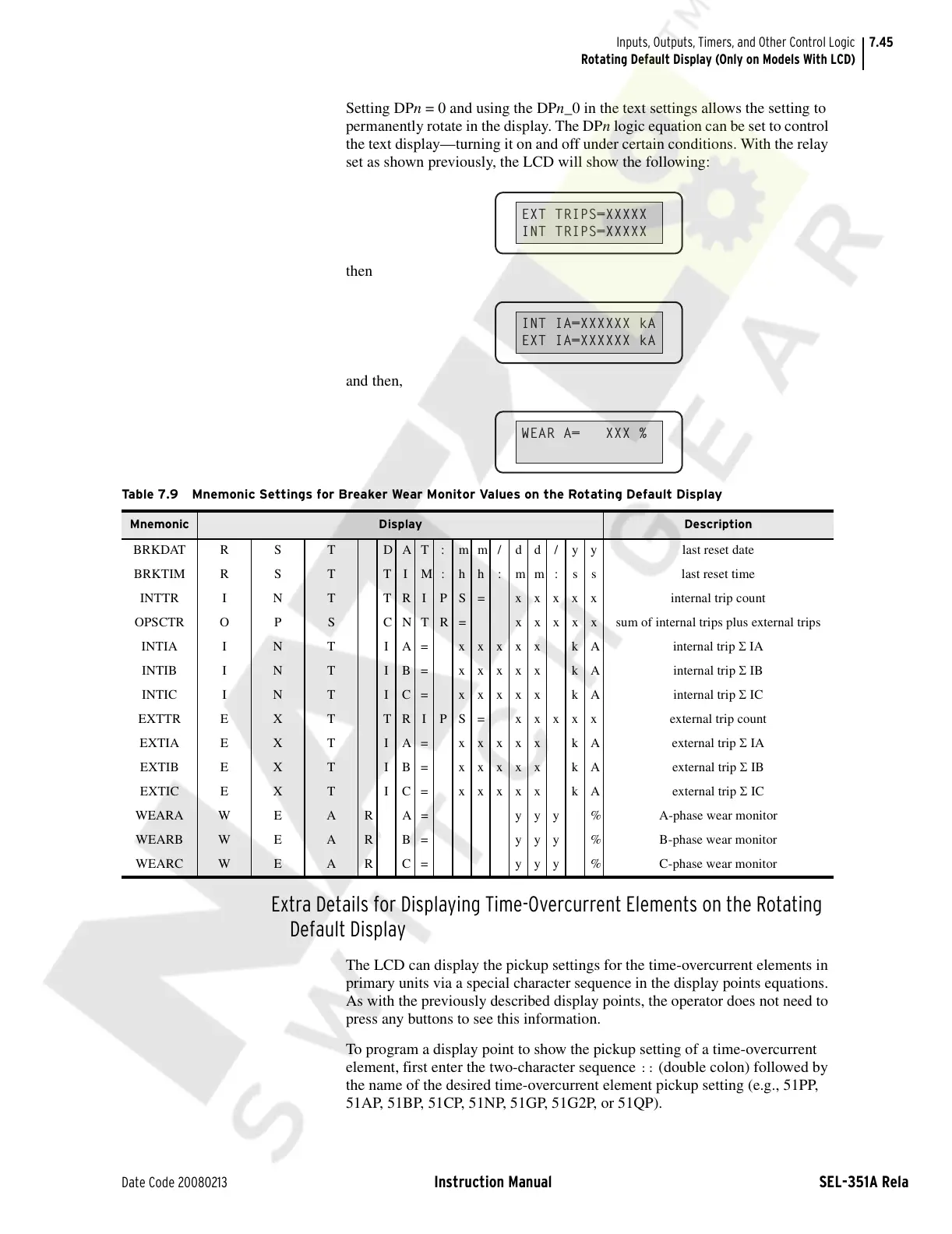
set as shown previously, the LCD will show the following:
then
and then,
Extra Details for Displaying Time-Overcurrent Elements on the Rotating
Default Display
The LCD can display the pickup settings for the time-overcurrent elements in
primary units via a special character sequence in the display points equations.
As with the previously described display points, the operator does not need to
press any buttons to see this information.
To program a display point to show the pickup setting of a time-overcurrent
element, first enter the two-character sequence
:: (double colon) followed by
the name of the desired time-overcurrent element pickup setting (e.g., 51PP,
51AP, 51BP, 51CP, 51NP, 51GP, 51G2P, or 51QP).
EXT TRIPS=XXXXX
INT TRIPS=XXXXX
INT IA=XXXXXX kA
EXT IA=XXXXXX kA
WEAR A= XXX %
Table 7.9 Mnemonic Settings for Breaker Wear Monitor Values on the Rotating Default Display
Mnemonic Display Description
BRKDAT R S T D A T : m m / d d / y y last reset date
BRKTIM R S T T I M : h h : m m : s s last reset time
INTTR I N T T R I P S = x x x x x internal trip count
OPSCTR O P S C N T R = x x x x x sum of internal trips plus external trips
INTIA I N T I A= xxxxx kA internal trip Σ IA
INTIB I N T IB= xxxxx kA internal trip Σ IB
INTIC I N T IC= xxxxx kA internal trip Σ IC
EXTTR E X T TRIPS= xxxxx external trip count
EXTIA E X T IA= xxxxx kA external trip Σ IA
EXTIB E X T IB= xxxxx kA external trip Σ IB
EXTIC E X T IC= xxxxx kA external trip Σ IC
WEARA W E A R A = y y y % A-phase wear monitor
WEARB W E A R B = y y y % B-phase wear monitor
WEARC W E A R C = y y y % C-phase wear monitor
Courtesy of NationalSwitchgear.com