3.24
SEL-351A Relay Instruction Manual Date Code 20080213
Overcurrent, Voltage, Synchronism Check, and Frequency Elements
Time-Overcurrent Elements
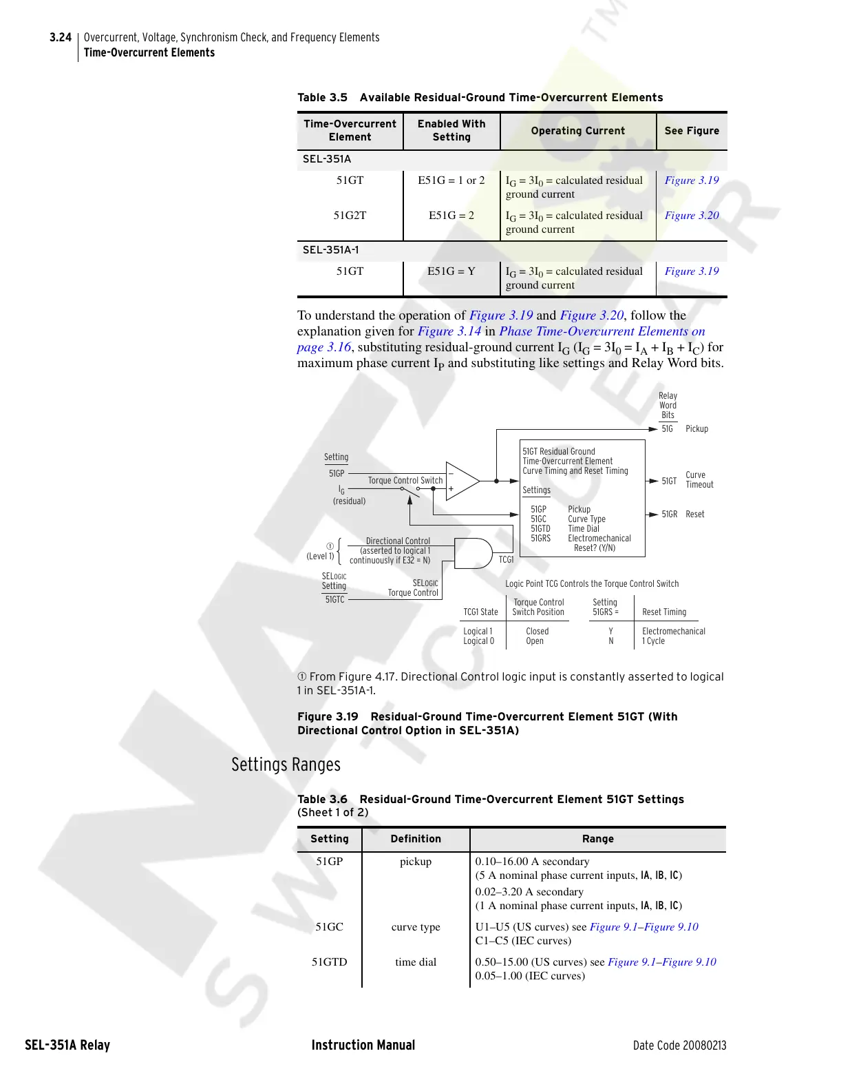
To understand the operation of Figure 3.19 and Figure 3.20, follow the
explanation given for Figure 3.14 in Phase Time-Overcurrent Elements on
page 3.16, substituting residual-ground current I
G
(I
G
= 3I
0
= I
A
+ I
B
+ I
C
) for
maximum phase current I
P
and substituting like settings and Relay Word bits.
q From Figure 4.17. Directional Control logic input is constantly asserted to logical
1 in SEL-351A-1.
Figure 3.19 Residual-Ground Time-Overcurrent Element 51GT (With
Directional Control Option in SEL-351A)
Settings Ranges
Table 3.5 Available Residual-Ground Time-Overcurrent Elements
Time-Overcurrent
Element
Enabled With
Setting
Operating Current See Figure
SEL-351A
51GT E51G = 1 or 2 I
G
= 3I
0
= calculated residual
ground current
Figure 3.19
51G2T E51G = 2 I
G
= 3I
0
= calculated residual
ground current
Figure 3.20
SEL-351A-1
51GT E51G = Y I
G
= 3I
0
= calculated residual
ground current
Figure 3.19
51GP
(residual)
I
G
Setting
51GTC
Torque Control Switch
Directional Control
(asserted to logical 1
continuously if E32 = N)
q
(Level 1)
SEL
OGIC
Torque Control
51GT Residual Ground
Time-Overcurrent Element
Curve Timing and Reset Timing
Settings
51GP Pickup
51GC Curve Type
51GTD Time Dial
51GRS Electromechanical
Reset? (Y/N)
Pickup
Curve
Timeout
Reset
51G
51GR
51GT
Torque Control
TCG1 State Switch Position
Logical 1 Closed
Logical 0 Open
Logic Point TCG Controls the Torque Control Switch
Setting
51GRS = Reset Timing
Y Electromechanical
N 1 Cycle
TCG1
Relay
Word
Bits
SELOGIC
Setting
Table 3.6 Residual-Ground Time-Overcurrent Element 51GT Settings
(Sheet 1 of 2)
Setting Definition Range
51GP pickup 0.10–16.00 A secondary
(5 A nominal phase current inputs, IA, IB, IC)
0.02–3.20 A secondary
(1 A nominal phase current inputs, IA, IB, IC)
51GC curve type U1–U5 (US curves) see Figure 9.1–Figure 9.10
C1–C5 (IEC curves)
51GTD time dial 0.50–15.00 (US curves) see Figure 9.1–Figure 9.10
0.05–1.00 (IEC curves)
Courtesy of NationalSwitchgear.com