4.30
SEL-351A Relay Instruction Manual Date Code 20080213
Loss-of-Potential, Load Encroachment, and Directional Element Logic
Directional Control for Negative-Sequence and Phase Overcurrent Elements (Not in SEL-351A-1)
Directional Control for Negative-Sequence and
Phase Overcurrent Elements (Not in SEL-351A-1)
The directional control for overcurrent elements is enabled by making
directional control enable setting E32. Setting E32 and other directional
control settings are described in Directional Control Settings (Not in
SEL-351A-1) on page 4.38.
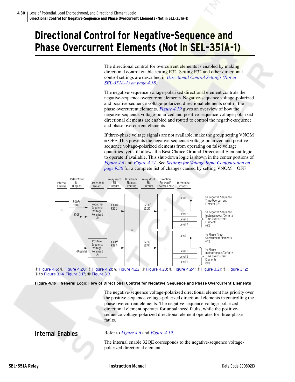
The negative-sequence voltage-polarized directional element controls the
negative-sequence overcurrent elements. Negative-sequence voltage-polarized
and positive-sequence voltage-polarized directional elements control the
phase overcurrent elements. Figure 4.19 gives an overview of how the
negative-sequence voltage-polarized and positive-sequence voltage-polarized
directional elements are enabled and routed to control the negative-sequence
and phase overcurrent elements.
If three-phase voltage signals are not available, make the group setting VNOM
= OFF. This prevents the negative-sequence voltage-polarized and positive-
sequence voltage-polarized elements from operating on false voltage
quantities, yet still allows the Best Choice Ground Directional Element logic
to operate if available. This shut-down logic is shown in the center portions of
Figure 4.6 and Figure 4.21. See Settings for Voltage Input Configuration on
page 9.36 for a complete list of changes caused by setting VNOM = OFF.
q Figure 4.6; w Figure 4.20; e Figure 4.21; r Figure 4.22; t Figure 4.23; y Figure 4.24; u Figure 3.21; i Figure 3.12;
o to Figure 3.14–Figure 3.17; a Figure 3.3.
Figure 4.19 General Logic Flow of Directional Control for Negative-Sequence and Phase Overcurrent Elements
The negative-sequence voltage-polarized directional element has priority over
the positive-sequence voltage-polarized directional elements in controlling the
phase overcurrent elements. The negative-sequence voltage-polarized
directional element operates for unbalanced faults, while the positive-
sequence voltage-polarized directional element operates for three-phase
faults.
Internal Enables
Refer to Figure 4.6 and Figure 4.19.
The internal enable 32QE corresponds to the negative-sequence voltage-
polarized directional element.
F32P/
R32P
F32Q/
R32Q
q
y
32QE
(Disable)
50QF/
50QR
to Phase Time-
Overcurrent Elements
(o)
to Phase
Instantaneous/Definite
Time Overcurrent
Elements
(a)
Level 1
32PF/
32PR
Negative-
Sequence
Voltage-
Polarized
w
Positive-
Sequence
Voltage-
Polarized
e
r
32QF/
32QR
t
Level 1
Level 2
Level 3
Level 4
to Negative-Sequence
Instantaneous/Definite
Time Overcurrent
Elements
(i)
Level 2
Level 3
Level 4
to Negative-Sequence
Time-Overcurrent
Element (u)
Internal
Enables
Relay Word
Bit
Outputs
Relay Word
Bit
Outputs
Relay Word
Bit
Outputs
Directional
Elements
Direction
Forward/
Reverse Logic
Directional
Control
Directional
Element
Routing
Courtesy of NationalSwitchgear.com