H.17
Date Code 20080213 Instruction Manual SEL-351A Relay
Distributed Network Protocol
Data Map
In standard mode, analog inputs are scanned at approximately a 1-second rate,
except for analogs 105–113. During a scan, all events generated will use the
time the scan was initiated. Analogs 105–113 are derived from the history
queue data for the most recently read fault. In standard mode, analogs 105–
113 do not generate event messages. In extended mode, events for these inputs
will use the time the scan was initiated. Analog input 115 is derived from the
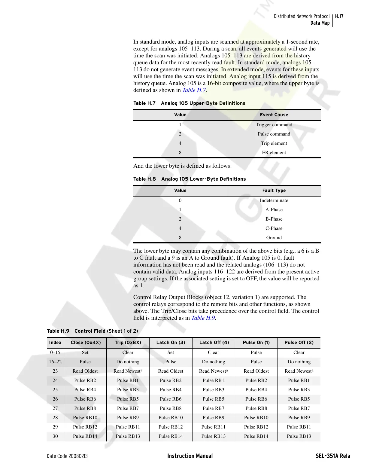
history queue. Analog 105 is a 16-bit composite value, where the upper byte is
defined as shown in Table H.7.
And the lower byte is defined as follows:
The lower byte may contain any combination of the above bits (e.g., a 6 is a B
to C fault and a 9 is an A to Ground fault). If Analog 105 is 0, fault
information has not been read and the related analogs (106–113) do not
contain valid data. Analog inputs 116–122 are derived from the present active
group settings. If the associated setting is set to OFF, the value will be reported
as 1.
Control Relay Output Blocks (object 12, variation 1) are supported. The
control relays correspond to the remote bits and other functions, as shown
above. The Trip/Close bits take precedence over the control field. The control
field is interpreted as in Tabl e H .9.
Table H.7 Analog 105 Upper-Byte Definitions
Value Event Cause
1 Trigger command
2 Pulse command
4 Trip element
8 ER element
Ta b le H . 8 A n a l o g 1 05 L o w e r -B y t e D e fini t i o n s
Value Fault Type
0 Indeterminate
1 A-Phase
2 B-Phase
4 C-Phase
8 Ground
Ta b le H . 9 Con t r o l Fi e ld (Sheet 1 of 2)
Index Close (0x4X) Trip (0x8X) Latch On (3) Latch Off (4) Pulse On (1) Pulse Off (2)
0–15 Set Clear Set Clear Pulse Clear
16–22 Pulse Do nothing Pulse Do nothing Pulse Do nothing
23 Read Oldest Read Newest
a
Read Oldest Read Newest
a
Read Oldest Read Newest
a
24 Pulse RB2 Pulse RB1 Pulse RB2 Pulse RB1 Pulse RB2 Pulse RB1
25 Pulse RB4 Pulse RB3 Pulse RB4 Pulse RB3 Pulse RB4 Pulse RB3
26 Pulse RB6 Pulse RB5 Pulse RB6 Pulse RB5 Pulse RB6 Pulse RB5
27 Pulse RB8 Pulse RB7 Pulse RB8 Pulse RB7 Pulse RB8 Pulse RB7
28 Pulse RB10 Pulse RB9 Pulse RB10 Pulse RB9 Pulse RB10 Pulse RB9
29 Pulse RB12 Pulse RB11 Pulse RB12 Pulse RB11 Pulse RB12 Pulse RB11
30 Pulse RB14 Pulse RB13 Pulse RB14 Pulse RB13 Pulse RB14 Pulse RB13
Courtesy of NationalSwitchgear.com