13.6
SEL-351A Relay Instruction Manual Date Code 20080213
Testing and Troubleshooting
Testing Methods and Tools
You can test the relay-processing module (via input J10) using signals from
the SEL-RTS Low-Level Relay Test System. Table 13.2 shows the resultant
signal scale factor information for the calibrated input module. These scale
factors are used in the SEL-5401 program, which is part of the SEL-RTS.
You can test the input module two different ways:
1. Measure the outputs from the input module with an accurate
voltmeter (measure signal pin to GND pin), and compare the
readings to accurate instruments in the relay input circuits, or
2. Replace the ribbon cable, press the front-panel {METER}
pushbutton, and compare the relay readings to other accurate
instruments in the relay input circuits.
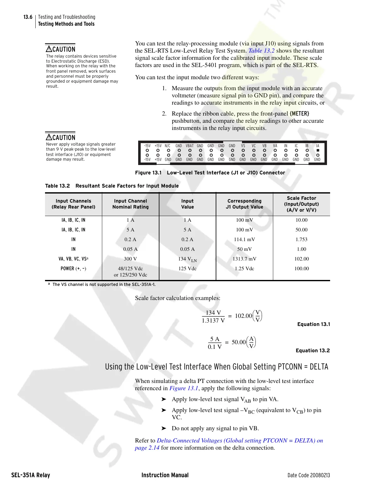
Figure 13.1 Low-Level Test Interface (J1 or J10) Connector
Scale factor calculation examples:
Equation 13.1
Equation 13.2
Using the Low-Level Test Interface When Global Setting PTCONN = DELTA
When simulating a delta PT connection with the low-level test interface
referenced in Figure 13.1, apply the following signals:
➤ Apply low-level test signal V
AB
to pin VA.
➤ Apply low-level test signal –V
BC
(equivalent to V
CB
) to pin
VC.
➤ Do not apply any signal to pin VB.
Refer to Delta-Connected Voltages (Global setting PTCONN = DELTA) on
page 2.14 for more information on the delta connection.
The relay contains devices sensitive
to Electrostatic Discharge (ESD).
When working on the relay with the
front panel removed, work surfaces
and personnel must be properly
grounded or equipment damage may
result.
!
CAUTION
GND
VBAT
GND GND
GNDGND
VSGNDGNDGND IA
GND
IBIC
GND GND
GND
VA
VB
GND
VC
GND
GND
GND
GND
GND
N/C
GND
+15V
+15V
–15V
–15V
IN
GND
Never apply voltage signals greater
than 9 V peak-peak to the low-level
test interface (J10) or equipment
damage may result.
!
CAUTION
Table 13.2 Resultant Scale Factors for Input Module
Input Channels
(Relay Rear Panel)
Input Channel
Nominal Rating
Input
Value
Corresponding
J1 Output Value
Scale Factor
(Input/Output)
(A/V or V/V)
IA, IB, IC, IN 1 A 1 A 100 mV 10.00
IA, IB, IC, IN 5 A 5 A 100 mV 50.00
IN 0.2 A 0.2 A 114.1 mV 1.753
IN 0.05 A 0.05 A 50 mV 1.00
VA, VB, VC, VS
a
a
The VS channel is not supported in the SEL-351A-1.
300 V 134 V
LN
1313.7 mV 102.00
POWER (+, –) 48/125 Vdc
or 125/250 Vdc
125 Vdc 1.25 Vdc 100.00
134 V
1.3137 V
---------------------- 102.00
V
V
----
⎝⎠
⎛⎞
=
5 A
0.1 V
------------- 50.00
A
V
----
⎝⎠
⎛⎞
=
Courtesy of NationalSwitchgear.com


 To Next Page