12.5
Date Code 20080213 Instruction Manual SEL-351A Relay
Standard Event Reports and SER
Standard 15/30-Cycle Event Reports
The event type designations AG through CAG in Table 12.1 are only entered in
the
Event field if the fault locator operates successfully. If the fault locator
does not operate successfully, just
TRIP or ER is displayed.
Fault Location
The relay reports the fault location if the EFLOC setting = Y and the fault
locator operates successfully after an event report is generated. If the fault
locator does not operate successfully,
$$$$$$ is listed in the field. If EFLOC =
N, the field is blank. Fault location is based upon the line impedance settings
Z1MAG, Z1ANG, Z0MAG, and Z0ANG; source impedance settings
Z0SMAG and Z0SANG; and corresponding line length setting LL. See the
SET command in Table 9.1 and corresponding Line Settings (See Settings
Explanations on page 9.34) on page SET.1 for information on the line
parameter settings.
The fault locator algorithm uses the overcurrent elements 50P1–50P4, 50N1–
50N4, 50G1–50G4, 67Q1–67Q4, 51P, 51A, 51B, 51C, 51N, 51G, 51G2, and
51Q as fault detectors. If any of these elements are set to low pickup values for
use as load indicators, they may be asserted during non-fault conditions. In
this situation, even though these elements are not being used for tripping the
relay, they may still affect the operation of the fault locator, because the start
of the disturbance may be unclear. If load detectors are required in your
application, use the highest-numbered instantaneous overcurrent elements
50P5, 50P6, 50N5, 50N6, 50G5, 50G6, 50Q5, or 50Q6, because these are not
used by the fault locator algorithm.
Targets
The relay reports the targets at the rising edge of TRIP. The targets include:
INST, COMM, S0TF, 50, 51, and 81. If there is no rising edge of TRIP in the
report, the
Targets field is blank. See Front-Panel Target LEDS on page 5.10.
Currents
The Currents (A pri), ABCNGQ: field shows the currents present in the event
report row containing the maximum phase current. The listed currents are:
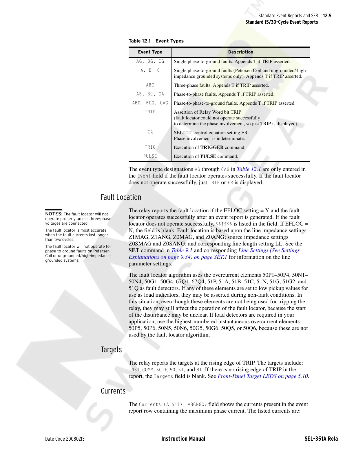
Ta b le 1 2 .1 Eve n t Ty pes
Event Type Description
AG, BG, CG
Single phase-to-ground faults. Appends T if TRIP asserted.
A, B, C
Single phase-to-ground faults (Petersen Coil and ungrounded/ high-
impedance grounded systems only). Appends T if TRIP asserted.
ABC
Three-phase faults. Appends T if TRIP asserted.
AB, BC, CA
Phase-to-phase faults. Appends T if TRIP asserted.
ABG, BCG, CAG
Phase-to-phase-to-ground faults. Appends T if TRIP asserted.
TRIP
Assertion of Relay Word bit TRIP
(fault locator could not operate successfully
to determine the phase involvement, so just TRIP is displayed).
ER
SELOGIC control equation setting ER.
Phase involvement is indeterminate.
TRIG
Execution of TRIGGER command.
PULSE
Execution of PULSE command.
NOTES: The fault locator will not
operate properly unless three-phase
voltages are connected.
The fault locator is most accurate
when the fault currents last longer
than two cycles.
The fault locator will not operate for
phase-to-ground faults on Petersen
Coil or ungrounded/high-impedance
grounded systems.
Courtesy of NationalSwitchgear.com