2.18
SEL-351A Relay Instruction Manual Date Code 20080213
Installation
Making Rear-Panel Connections
To verify the correct polarity on voltage input VS-NS, perform the following
test on the primary side of one of the PTs connected in broken-delta secondary
(refer to Figure 2.10) and observe the resultant voltage phase angle
differences:
Open circuit the primary side of the PT connected to power system
phase A. With the resultant collapse of secondary voltage V
A
(V
A
= 0) in
the broken-delta secondary circuit, the voltage at voltage input VS-NS is:
V
S
= 3V
0
= V
A
+ V
B
+ V
C
= V
B
+ V
C
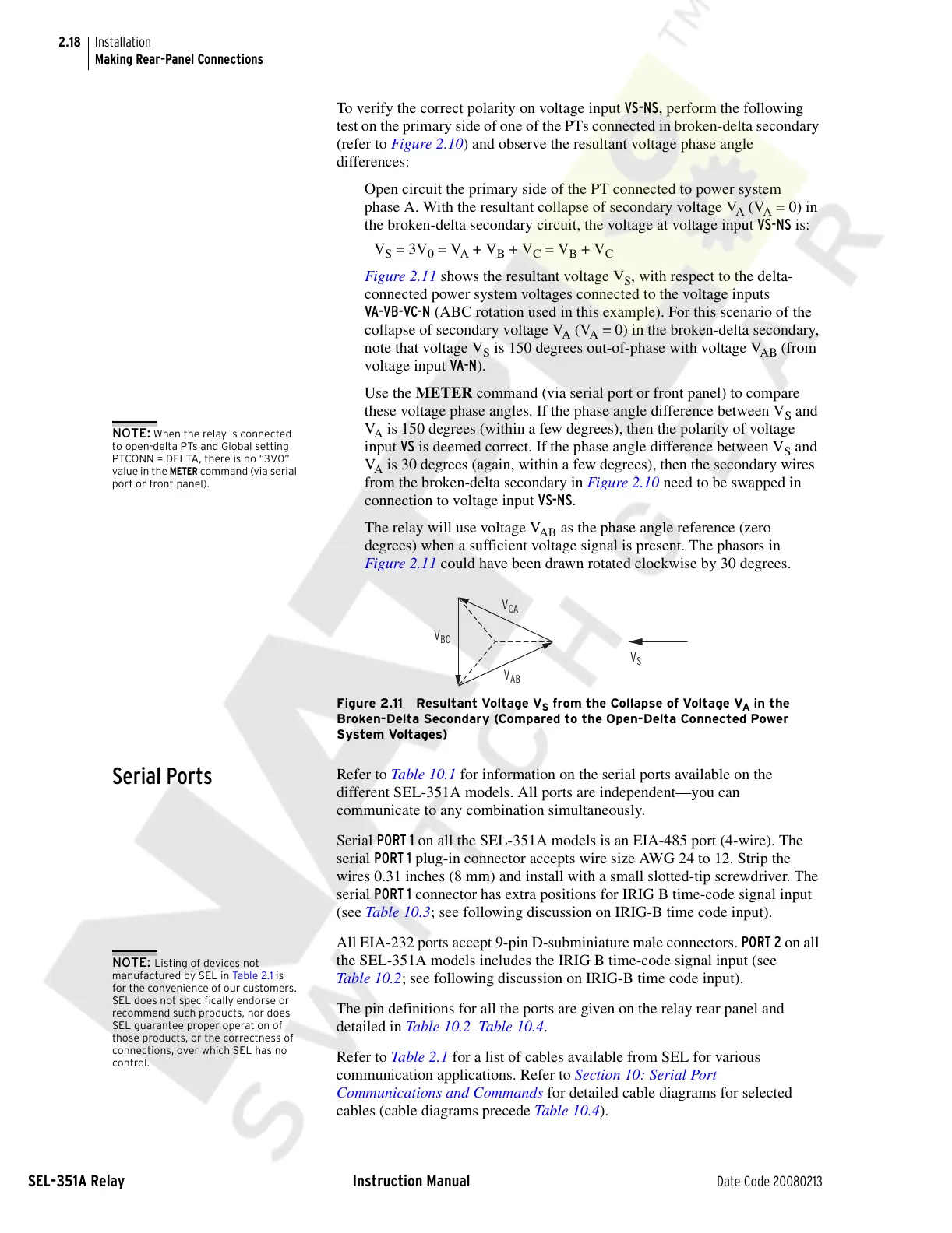
Figure 2.11 shows the resultant voltage V
S
, with respect to the delta-
connected power system voltages connected to the voltage inputs
VA-VB-VC-N (ABC rotation used in this example). For this scenario of the
collapse of secondary voltage V
A
(V
A
= 0) in the broken-delta secondary,
note that voltage V
S
is 150 degrees out-of-phase with voltage V
AB
(from
voltage input VA-N).
Use the METER command (via serial port or front panel) to compare
these voltage phase angles. If the phase angle difference between V
S
and
V
A
is 150 degrees (within a few degrees), then the polarity of voltage
input VS is deemed correct. If the phase angle difference between V
S
and
V
A
is 30 degrees (again, within a few degrees), then the secondary wires
from the broken-delta secondary in Figure 2.10 need to be swapped in
connection to voltage input VS-NS.
The relay will use voltage V
AB
as the phase angle reference (zero
degrees) when a sufficient voltage signal is present. The phasors in
Figure 2.11 could have been drawn rotated clockwise by 30 degrees.
Figure 2.11 Resultant Voltage V
S
from the Collapse of Voltage V
A
in the
Broken-Delta Secondary (Compared to the Open-Delta Connected Power
System Voltages)
Serial Ports
Refer to Table 10.1 for information on the serial ports available on the
different SEL-351A models. All ports are independent—you can
communicate to any combination simultaneously.
Serial PORT 1 on all the SEL-351A models is an EIA-485 port (4-wire). The
serial PORT 1 plug-in connector accepts wire size AWG 24 to 12. Strip the
wires 0.31 inches (8 mm) and install with a small slotted-tip screwdriver. The
serial PORT 1 connector has extra positions for IRIG B time-code signal input
(see Table 10.3; see following discussion on IRIG-B time code input).
All EIA-232 ports accept 9-pin D-subminiature male connectors. PORT 2 on all
the SEL-351A models includes the IRIG B time-code signal input (see
Table 10.2; see following discussion on IRIG-B time code input).
The pin definitions for all the ports are given on the relay rear panel and
detailed in Table 1 0.2–Table 10.4.
Refer to Table 2 .1 for a list of cables available from SEL for various
communication applications. Refer to Section 10: Serial Port
Communications and Commands for detailed cable diagrams for selected
cables (cable diagrams precede Tab le 10.4).
NOTE: When the relay is connected
to open-delta PTs and Global setting
PTCONN = DELTA, there is no “3V0”
value in the METER command (via serial
port or front panel).
V
CA
V
BC
V
AB
V
S
NOTE: Listing of devices not
manufactured by SEL in Tab le 2 .1 is
for the convenience of our customers.
SEL does not specifically endorse or
recommend such products, nor does
SEL guarantee proper operation of
those products, or the correctness of
connections, over which SEL has no
control.
Courtesy of NationalSwitchgear.com