2.27
Date Code 20080213 Instruction Manual SEL-351A Relay
Installation
SEL-351A AC/DC Connection Diagrams for Various Applications
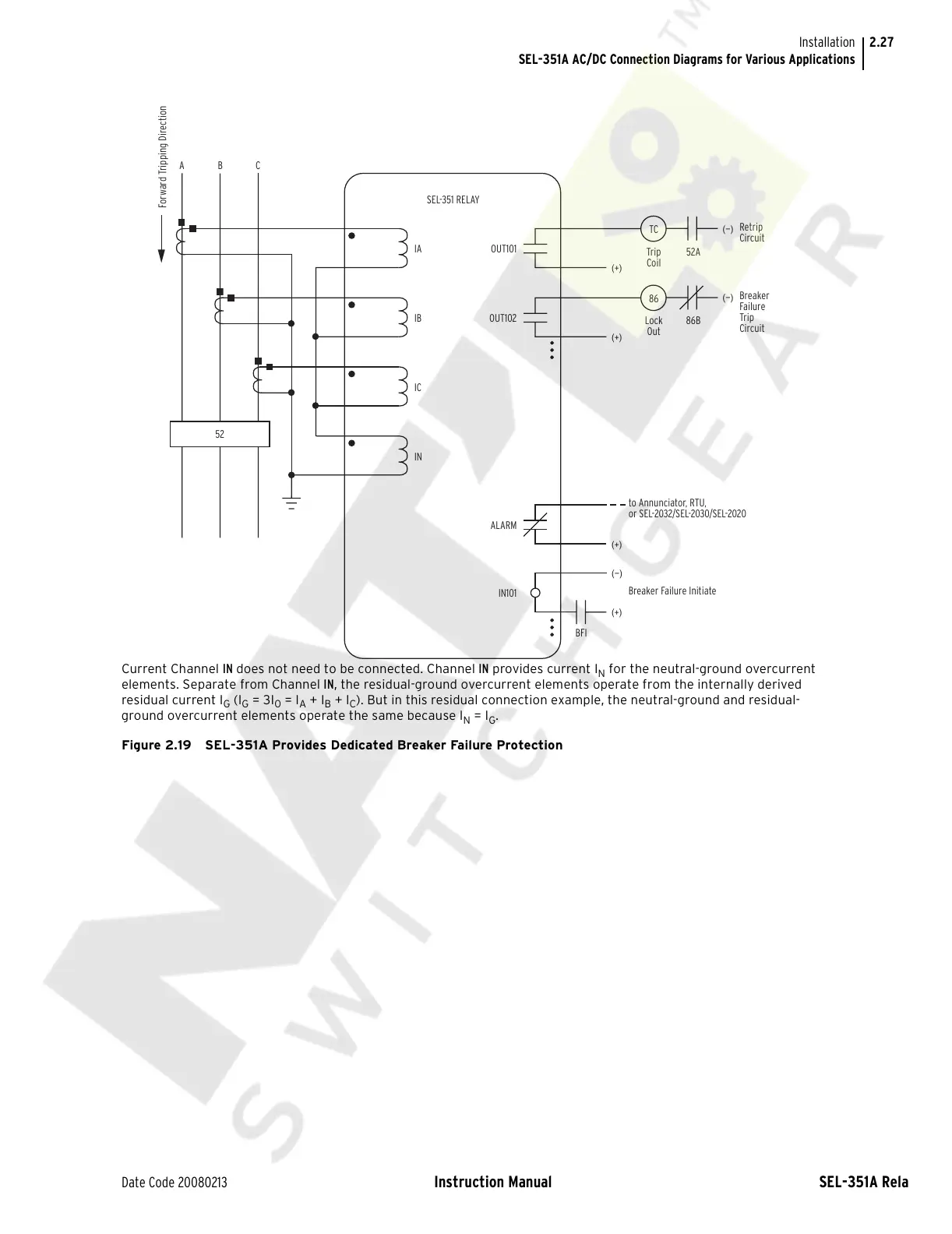
Current Channel IN does not need to be connected. Channel IN provides current I
N
for the neutral-ground overcurrent
elements. Separate from Channel IN, the residual-ground overcurrent elements operate from the internally derived
residual current I
G
(I
G
= 3I
0
= I
A
+ I
B
+ I
C
). But in this residual connection example, the neutral-ground and residual-
ground overcurrent elements operate the same because I
N
= I
G
.
Figure 2.19 SEL-351A Provides Dedicated Breaker Failure Protection
TC
Trip
Coil
52A
(+)
(—)
Retrip
Circuit
IA
CBA
SEL-351 RELAY
OUT101
Forward Tripping Direction
86
Lock
Out
86B
(+)
(—)
Breaker
Failure
Trip
Circuit
IB
OUT102
IC
IN
52
(+)
BFI
to Annunciator, RTU,
or SEL-2032/SEL-2030/SEL-2020
ALARM
(+)
(—)
Breaker Failure Initiate
IN101
Courtesy of NationalSwitchgear.com