D.5
Date Code 20080213 Instruction Manual SEL-351A Relay
Configuration, Fast Meter, and Fast Operate Commands
Message Definitions
A5D1 Fast Meter Data
Block
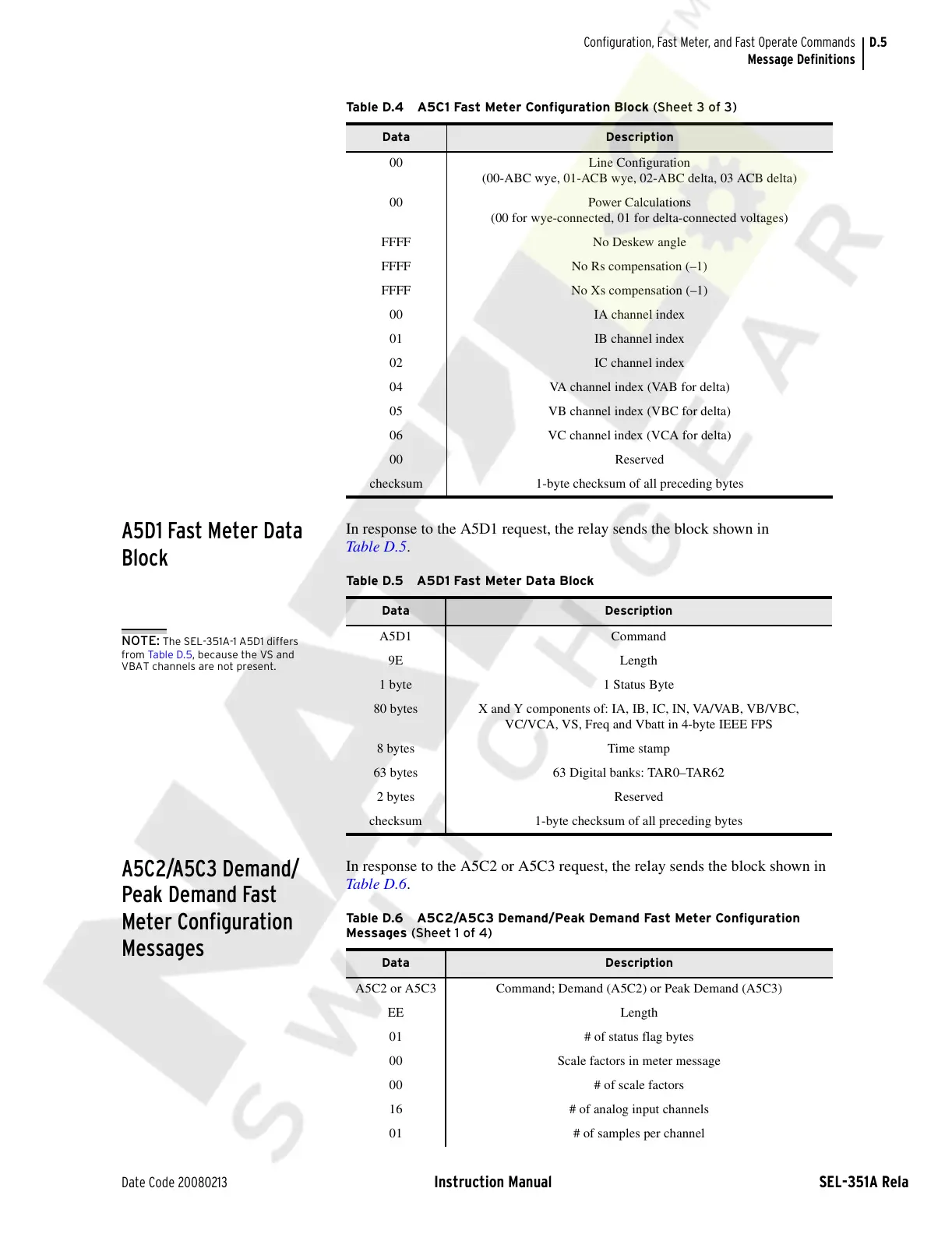
In response to the A5D1 request, the relay sends the block shown in
Table D.5.
A5C2/A5C3 Demand/
Peak Demand Fast
Meter Configuration
Messages
In response to the A5C2 or A5C3 request, the relay sends the block shown in
Table D.6.
00 Line Configuration
(00-ABC wye, 01-ACB wye, 02-ABC delta, 03 ACB delta)
00 Power Calculations
(00 for wye-connected, 01 for delta-connected voltages)
FFFF No Deskew angle
FFFF No Rs compensation (–1)
FFFF No Xs compensation (–1)
00 IA channel index
01 IB channel index
02 IC channel index
04 VA channel index (VAB for delta)
05 VB channel index (VBC for delta)
06 VC channel index (VCA for delta)
00 Reserved
checksum 1-byte checksum of all preceding bytes
Table D.4 A5C1 Fast Meter Configuration Block (Sheet 3 of 3)
Data Description
Table D.5 A5D1 Fast Meter Data Block
Data Description
A5D1 Command
9E Length
1 byte 1 Status Byte
80 bytes X and Y components of: IA, IB, IC, IN, VA/VAB, VB/VBC,
VC/VCA, VS, Freq and Vbatt in 4-byte IEEE FPS
8 bytes Time stamp
63 bytes 63 Digital banks: TAR0–TAR62
2 bytes Reserved
checksum 1-byte checksum of all preceding bytes
NOTE: The SEL-351A-1 A5D1 differs
from Ta ble D. 5, because the VS and
VBAT channels are not present.
Table D.6 A5C2/A5C3 Demand/Peak Demand Fast Meter Configuration
Messages (Sheet 1 of 4)
Data Description
A5C2 or A5C3 Command; Demand (A5C2) or Peak Demand (A5C3)
EE Length
01 # of status flag bytes
00 Scale factors in meter message
00 # of scale factors
16 # of analog input channels
01 # of samples per channel
Courtesy of NationalSwitchgear.com